Cement plant pressure fan energy-saving control system

An energy-saving control system and compressor technology, applied in pump control, mechanical equipment, machines/engines, etc., can solve the problems of unstable speed, inability to save energy, and low precision of speed regulation, so as to solve the problem of start-up shock and improve the effective Utilization, the effect of wide range stepless speed regulation

Inactive Publication Date: 2013-08-21
SINOMA SUZHOU CONSTR
View PDF0 Cites 2 Cited by
  • Summary
  • Abstract
  • Description
  • Claims
  • Application Information

AI Technical Summary

Problems solved by technology

The disadvantage of the throttling method is that part of the energy is consumed on the valve, the slip loss is large, the efficiency is low, and the energy waste is serious.
The disadvantage of the start-up speed regulation method of hydraulic coupling plus liquid rheostat is that the speed of the output end of the motor does not change during the speed regulation process, so the required power does not change, which can only achieve the purpose of speed regulation and cannot achieve energy saving. Power and mechanical losses will be generated in the process, and a large amount of heat will be generated with the loss, which requires water cooling
At the same time, there are also phenomena such as low speed regulation accuracy, slow speed response and unstable speed.

Method used


Image

  • Cement plant pressure fan energy-saving control system

Examples


Embodiment Construction

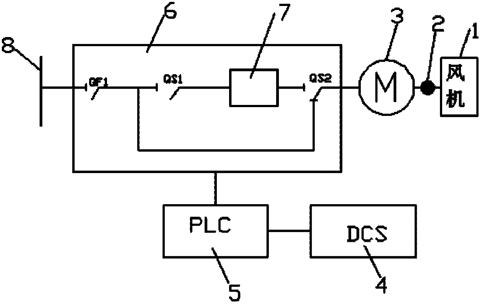
[0014] An energy-saving control system for a pressurized fan in a cement plant, including a fan 1, a universal joint coupling 2, a motor 3, a distributed control system (DCS) signal converter 4, a programmable logic controller (PLC) 5, and a motor drive controller 6. The distributed control system signal converter, programmable controller, motor drive controller, motor, universal joint coupling and fan are connected in sequence, and the motor drive controller includes a first switch QF1, a second switch QS1, the third switch QS2 and the frequency converter 7, the third switch is a single-pole double-throw switch, one end of the first switch is connected to the high-voltage bus 8, and the other end of the first switch is respectively connected to one end of the second switch and the first One static contact of the three switches, the other end of the second switch is connected to one end of the frequency converter, the other end of the frequency converter is connected to the oth...


PUM


Abstract

The invention discloses a cement plant pressure fan energy-saving control system. The cement plant pressure fan energy-saving control system comprises a fan, a universal joint coupling, a motor, a distributed control system signal converter, a PLC (programmable logic controller) and a motor driving controller, wherein the distributed control system signal converter, the PLC, the motor driving controller, the motor, the universal joint coupling and the fan are connected sequentially; and the motor driving controller comprises a first switch, a second switch, a third switch and a frequency converter, the third switch is a single-pole double-throw switch, one end of the first switch is connected with a high-voltage bus, the other end of the first switch is connected with one end of the second switch and a fixed contact of the third switch respectively, the other end of the second switch is connected with one end of the frequency converter, the other end of the frequency converter is connected with the other fixed contact of the third switch, and a moving contact of the third switch is sequentially connected with the motor, the universal joint coupling and the fan. The cement plant pressure fan energy-saving control system can achieve the stepless changing of the rotating speed of the fan, thereby adjusting the air quantity and air pressure of the fan accurately, improving the operating efficiency of the fan and reducing the energy consumption of the fan remarkably.

Description

technical field [0001] The invention relates to an energy-saving control system for a fan, in particular to an energy-saving control system for a pressurized fan in a cement plant. Background technique [0002] The cement industry is a large energy consumer. In the process of cement production, the fans of the grinding and firing systems involved in the adjustment of working conditions consume a lot of power, and the power consumption of fans accounts for about 30%-40% of the total power consumption. With the increasing use of roller mill systems, the proportion of power consumption of fans is increasing, especially medium pressure fans. The type selection of the fan is designed according to the full load state, but in the actual production process, the change of working conditions and output will cause the random adjustment of the air volume and air pressure. At present, the commonly used fan adjustment methods are throttling method and hydraulic coupling. The start-up spe...

Claims


Application Information

Patent Timeline
Patent Type & Authority Applications(China)
IPC IPC(8): F04D27/00
Inventor 刘仁越刘玉中
Owner SINOMA SUZHOU CONSTR
Why Eureka
Try Eureka