Tensioner

a technology of tensioner and tensioner plate, which is applied in the direction of belt/chain/gearing, mechanical equipment, belt/chain/gearing, etc., can solve the problems of transmission chain vibration and transmission chain damage, and achieve satisfactory damping effect, increase the capacity of oil storage chamber, and improve the stability of the installation state of the check valv

Active Publication Date: 2020-06-16
TSUBAKIMOTO CHAIN CO
View PDF12 Cites 0 Cited by
  • Summary
  • Abstract
  • Description
  • Claims
  • Application Information

AI Technical Summary

Benefits of technology

[0010]It is therefore an object of the present invention to provide a tensioner which can solve these problems and can ensure, with a simple structure, both the stability of the installation state of the check valve and the capacity of the oil storage chamber.
[0012]According to one aspect of the present invention, the pressing front end portion that defines the front end side of the oil storage chamber and presses the pressing object, and the valve movement restricting portion that restricts the movement of the check valve to the front side are formed separately on the front-side plunger part and the rear side plunger part which are separate parts. As a result, the rear-side plunger part having the valve movement restricting part can be machined from both the front side and the rear side. Therefore, restrictions on the dimensional design between the radial width dimension of the valve movement restricting portion and the inner diameter of the oil storage chamber which are applied when the plunger is formed as a part are eliminated, the radial width dimension of the valve movement restricting portion can be designed to be large, the stability of the installation state of the check valve can be increased, and the capacity of the oil storage chamber can be increased.
[0013]According to another aspect of the present invention, the rear-side sliding cylindrical portion of the rear-side plunger part includes a first cylindrical part located further toward the front side than the valve movement restricting part, and the second cylindrical part located further toward the rear side than the valve movement restricting part, thereby making it possible to ensure a large dimension of the rear-side sliding cylindrical portion in the front-rear direction. This makes it possible to configure the outer peripheral surface on the rear side of the plunger, which strongly influences the damping effect, of the rear-side plunger part which is the same part, so that it is possible to form smoothly the outer peripheral surface on the rear side of the plunger and obtain a satisfactory damping effect.
[0014]According to another aspect of the present invention, the front-side plunger part and the rear-side plunger part each have a sliding cylindrical portion, so that the dimension of each sliding cylindrical portion of each plunger part can be shortened. Therefore, machining of each plunger part is facilitated, for example, the dig-down amount of each sliding cylindrical portion can be reduced.
[0015]According to another aspect of the present invention, since the pressing front end portion is fitted to the front end side of the first cylindrical portion, sliding against the inner peripheral surface of the plunger accommodating hole can be performed on the rear-side sliding cylindrical portion of the rear-side plunger part. Therefore, it is not necessary to impart a sliding characteristic to the front-side plunger part, and it is possible to improve the degree of freedom in designing the material of the front-side plunger part.
[0016]According to another aspect of the present invention, as a result of forming the valve movement restricting portion on the front end side of the rear-side sliding cylindrical portion, it is not necessary to form a sliding cylindrical portion on both the front side and the rear side with respect to the valve movement restricting portion of the rear-side plunger part, thereby making it possible to facilitate the machining of the rear-side plunger part.

Problems solved by technology

As a result, the damping force produced by the oil does not act on the plunger and vibrations of the transmission chain can increase or the transmission chain can be damaged.

Method used


Image

  • Tensioner
  • Tensioner
  • Tensioner

Examples


first embodiment

[0027]A tensioner 10 according to the present invention will be described hereinbelow with reference to the figures.

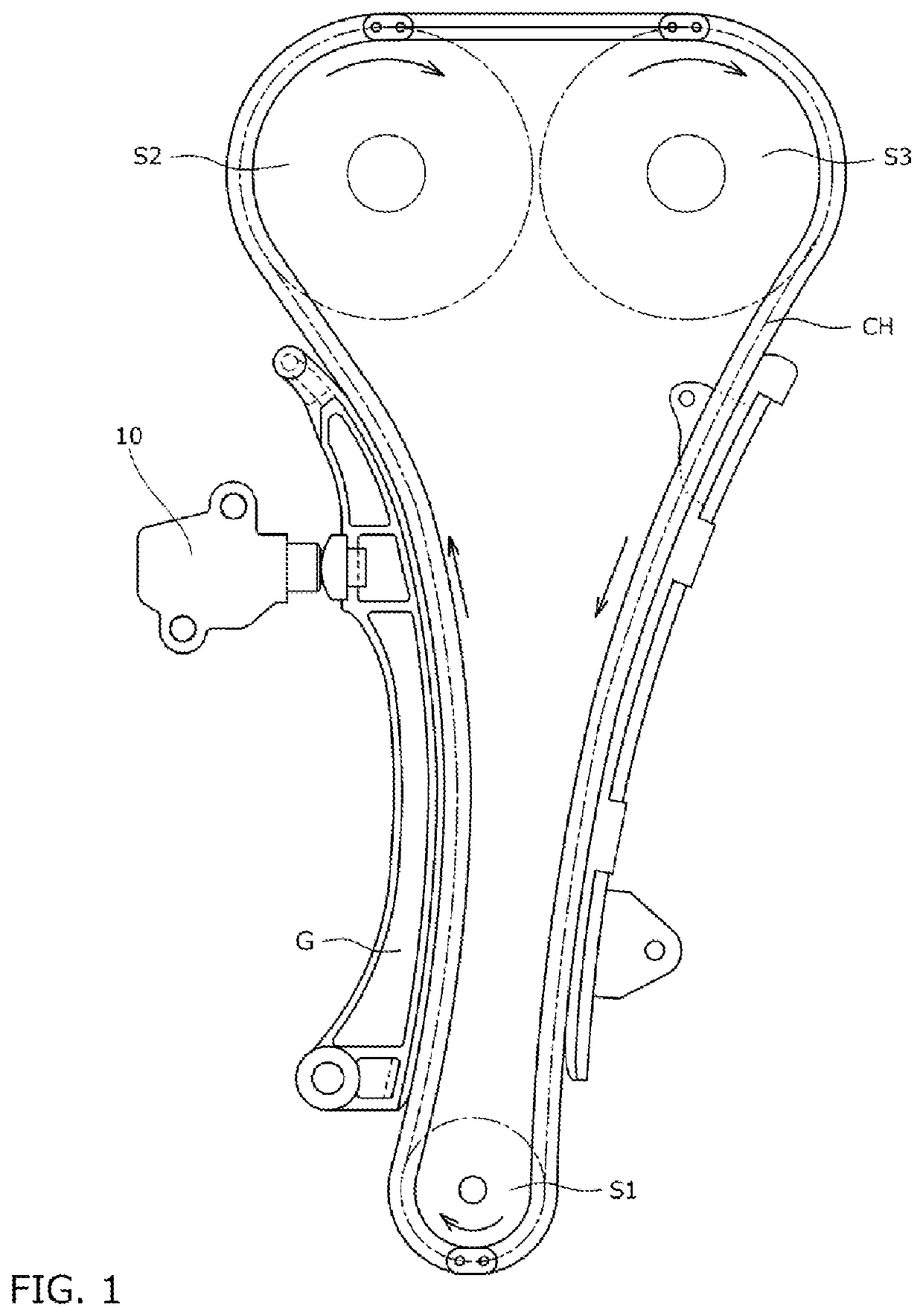
[0028]First, as shown in FIG. 1, a tensioner 10 is incorporated in a chain transmission device used, for example, for a timing system of an automobile engine, and is attached to an engine block (not shown in the figure). The tensioner applies, through a tensioner lever G, appropriate tension to the slack side of a transmission chain CH wound on a plurality of sprockets S1 to S3, thereby suppressing vibrations occurring when the automobile travels.

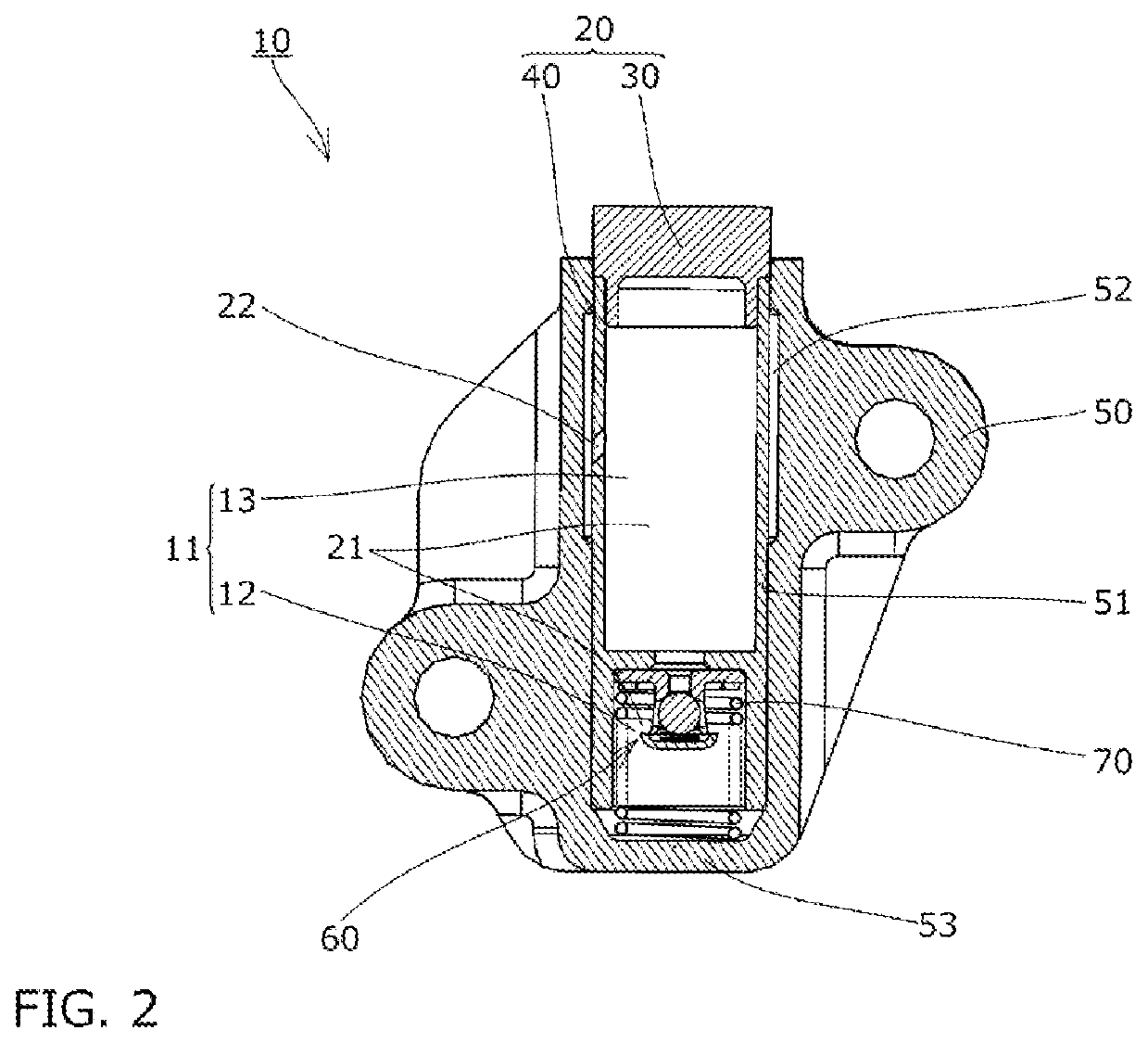
[0029]As shown in FIG. 2, the tensioner 10 includes a plunger 20 having a plunger hole 21 opened to the rear side, a housing 50 having a plunger accommodating hole 51 opened to the front side and accommodating the plunger 20, a check valve 60 that allows oil to flow from an oil storage chamber 13 on the front side, which is formed in an internal space 11 between the housing 50 and the plunger 20, into a pressure oil chamber 12...

second embodiment

[0045]In the second embodiment, as shown in FIG. 5, the front-side plunger part 30 has the pressing front end portion 31, the front-side sliding cylindrical portion 32 which is formed so as to protrude from the rear surface of the pressing front end portion 31 toward the rear side and is slidably disposed on the inner peripheral surface of the plunger accommodating hole 51, and an annular fitting protruding portion 33 formed to protrude from the rear surface of the front-side sliding cylindrical portion 32 toward the rear side.

[0046]Further, in the second embodiment, the plunger through hole 22 passing through from the outer peripheral side to the inner peripheral side is formed in the front-side sliding cylindrical portion 32.

[0047]Further, as shown in FIG. 5, the outer peripheral surfaces of the pressing front end portion 31 and the front-side sliding cylindrical portion 32 are formed flush with the outer peripheral surface of the rear-side sliding cylindrical portion 41. The oute...

third embodiment

[0050]First, in the third embodiment, as shown in FIG. 6, the fitting protruding portion 33 is not formed at the front-side plunger part 30.

[0051]Further, the first cylindrical portion 41a is not formed at the rear-side sliding cylindrical portion 41 of the rear-side plunger part 40, and an annular fitting protruding portion 43 formed to protrude from the front surface of the rear-side sliding cylindrical portion 41 toward the front side is formed at the rear-side plunger part 40.

[0052]Further, as shown in FIG. 6, the outer peripheral surfaces of the pressing front end portion 31 and the front-side sliding cylindrical portion 32 are formed flush with the outer peripheral surface of the rear-side sliding cylindrical portion 41. The outer diameter dimensions of the pressing front end portion 31, the front-side sliding cylindrical portion 32, and the rear-side sliding cylindrical portion 41 may be set so that the outer peripheral surfaces of the pressing front end portion 31 and the fr...


PUM


Abstract

Provided is a tensioner which can ensure, with a simple structure, both the stability of the installation state of a check valve and the capacity of an oil storage chamber. A tensioner has a plunger, a housing, a check valve, and a coil spring. The plunger has a front-side plunger part having a pressing front end portion, and a rear-side plunger part disposed on the rear side of the front-side plunger part and having a valve movement restricting portion. The check valve is disposed on the rear side of the valve movement restricting portion. The coil spring is disposed so that one end thereof is in contact with a housing bottom portion and the other end thereof is in contact with the rear side of the check valve.

Description

BACKGROUND OF THE INVENTION1. Field of the Invention[0001]The present invention relates to a tensioner that is used to apply an appropriate tension to a transmission belt or a transmission chain in an engine timing system or the like, and more particularly relates to a tensioner including an oil storage chamber that supplies oil to a pressure oil chamber.2. Description of the Related Art[0002]Conventionally, it has been customary to use a tensioner to hold the tension of a chain or the like. For example, it is well known to bias a tensioner lever with a tensioner in order to hold appropriately the tension in a chain guide mechanism which slidably guides by a tensioner lever a transmission chain, such as a roller chain, that is endlessly suspended between sprockets provided on a crankshaft and a camshaft in an engine room.[0003]A known tensioner used for such a chain guide mechanism includes a plunger having a plunger hole opened to the rear side, a housing having a plunger accommoda...

Claims


Application Information

Patent Timeline
Patent Type & Authority Patents(United States)
IPC IPC(8): F16H7/08
CPCF16H7/0836F16H7/0848F16H2007/0872F16H2007/0897F16H2007/0893F16H2007/0859F16H2007/0812F16H7/08F16H2007/0891F16H2007/0806F16H7/0838
Inventor MAEDA, MUNEHIROKUREMATSU, YUJIYOSHIDA, OSAMUTAKAGI, YUDAI
Owner TSUBAKIMOTO CHAIN CO
Why Eureka
Try Eureka