Brushless motor control device

a motor control and brushless technology, applied in the direction of machines/engines, mechanical equipment, radial flow pumps, etc., can solve the problems of misdetection of zero crossing, unexpected fluctuation of voltage called “return current”, damage to the semiconductor configuring the hall sensor,

Active Publication Date: 2020-06-16
DENSO CORP
View PDF10 Cites 0 Cited by
  • Summary
  • Abstract
  • Description
  • Claims
  • Application Information

AI Technical Summary

Benefits of technology

[0013]The present disclosure is to provide a brushless motor control device that may promptly normalizes rotation control of the motor in a case in which an abnormality in detection of rotation position of the rotor has been detected.
[0019]According to the brushless motor control device of the third aspect, in a case in which zero crossings are detected two times in succession immediately after the elapse of the predetermined masking period at which the effect of return current would be eliminated, this detection is taken as abnormal detection of rotor rotation position. Accordingly, the third aspect of the present disclosure may promptly detect the step out in the motor, and may promptly normalize the rotation control of the motor.
[0021]According to the brushless motor control device of the fourth aspect, by determining the current-on phase of the three phase motor based on first detected zero crossing after current-on interruption, rotation control of the motor may be rapidly normalized.
[0023]According to the brushless motor control device of the fifth aspect, by determining the current-on phase based on the zero crossing detected two or more times after current-on interruption, the effect of return current may be completely eliminated, and detection of rotation position of the rotor may become accurate.

Problems solved by technology

However, Hall sensors are semiconductor elements and so are intolerant of heat.
Accordingly, the semiconductors configuring the Hall sensors may be damaged in the high temperature environment inside the engine compartment.
However, immediately after interrupting current-on to a coil of the motor, there are cases in which unexpected fluctuation in voltage called “return current” occurs due to counter-electromotive force.
This results in misdetection of zero crossing.

Method used


Image

  • Brushless motor control device
  • Brushless motor control device
  • Brushless motor control device

Examples


Embodiment Construction

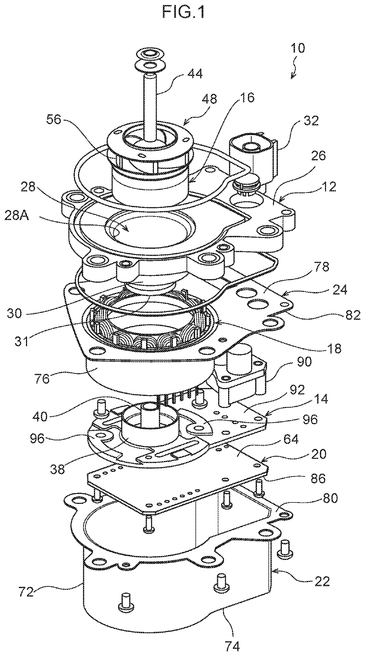
[0032]FIG. 1 is an exploded perspective view of a pump drive motor 10 (hereafter abbreviated to “motor 10”) according to the present exemplary embodiment. As illustrated in FIG. 1, the motor 10 includes a housing 12, a base member 14, a rotor 16, a stator 18, a control board 20, a shield cover 22, and a stator holder 24.

[0033]The housing 12 is made from a resin. The housing 12 includes a single body configured by a plate shaped housing body 26, and by a peripheral wall 30 of a rotor housing chamber 28 that houses the rotor 16 and includes an opening 28A. A connector 32 is provided at one end of the housing body 26, and the peripheral wall 30 of the rotor housing chamber 28 is formed in a cylindrical shape at positions further toward the other end of the housing body 26 than a central portion thereof.

[0034]The motor 10 is, for example, suitably applied to a water pump that circulates engine cooling water. The rotor housing chamber 28 is in communication with a pump chamber formed in ...


PUM


Abstract

In a brushless motor control device, a microcontroller determines a current-on phase of a motor based on zero crossing detected by a position detection circuit, and the inverter circuit generates a voltage for current-on to the determined current-on phase. In a case in which zero crossing has been successively detected plural times, in a phase that was switched from the current-on phase to a current-off phase, in a PWM control cycle after a predetermined masking period, the microcontroller controls to interrupt current to coils of all phases of the motor body. In a state in which current-on has been interrupted, the microcontroller determines the current-on phase based on zero crossing detected in one of the three phases, the inverter circuit generates the voltage for current-on for the determined current-on phase and restarts current-on to the coils.

Description

CROSS-REFERENCE TO RELATED APPLICATION[0001]This application claims priority under 35 USC 119 from Japanese Patent Application No. 2018-080933, filed on Apr. 19, 2018, the disclosure of which is incorporated by reference herein.BACKGROUNDTechnical Field[0002]The present disclosure relates to a brushless motor control device for driving a vehicle water pump or the like.Related Art[0003]In a water cooled engine, an engine is cooled by circulating cooling water including antifreeze liquid in a water jacket. The water jacket is provided to an engine block or the like and configures a flow path for the cooling water. A water pump is attached to the engine block of a water cooled engine to circulate the cooling water, and the water pump is driven by a pump drive motor having a power supply controlled by an electronic control unit (ECU) provided in a vehicle.[0004]The flow rate of the cooling water needs to be appropriate in order to cool the engine effectively. In recent years brushless m...

Claims


Application Information

Patent Timeline
Patent Type & Authority Patents(United States)
IPC IPC(8): H02P23/14F04D1/00F04D13/06H02P25/03
CPCH02P23/14F04D13/0606H02P25/03F04D1/00F04D15/0066H02P6/157
Inventor MATSUMOTO, MASAKAZU
Owner DENSO CORP
Why Eureka
Try Eureka