Actuators and methods for aircraft flight control surfaces

a technology for aircraft flight control and actuators, which is applied in the direction of belts/chains/gearrings, toothed gearings, aircraft transmission means, etc., can solve the problems of mechanical jam potential, emas that are not typically used to actuate the primary flight control surface of aircraft, and existing emas that do not provide the same level of reliability

Active Publication Date: 2020-06-23
BOMBARDIER INC +1
View PDF18 Cites 4 Cited by
  • Summary
  • Abstract
  • Description
  • Claims
  • Application Information

AI Technical Summary

Benefits of technology

[0016]The first screw may be mounted to substantially prevent rotation of the first screw relative to the aircraft structure.
[0017]The second screw may be mounted to substantially prevent rotation of the second screw relative to the first screw.
[0028]The first screw may be mounted to substantially prevent rotation of the first screw relative to the aircraft structure.
[0029]The second screw may be mounted to substantially prevent rotation of the second screw relative to the first screw.
[0059]At least partially disengaging the second screw from the first screw may comprise reducing an amount of magnetic flux passing through magneto-rheological fluid.
[0069]controlling the yield shear strength of the magneto-rheological fluid to control the stiffness of the actuator and thereby control damping of the of the flight control surface.

Problems solved by technology

Although electromechanical actuators (EMAs) have some operational advantages over hydraulic actuators, EMAs are still not typically used to actuate primary flight controls surfaces of aircraft.
One reason for this is that existing EMAs do not provide the same level of reliability as that associated with hydraulic actuators.
For example, some existing EMAs may come with a potential risk of mechanical jam which may contribute to the lower level of reliability in comparison with hydraulic actuators.

Method used


Image

  • Actuators and methods for aircraft flight control surfaces
  • Actuators and methods for aircraft flight control surfaces
  • Actuators and methods for aircraft flight control surfaces

Examples


Embodiment Construction

[0084]Aspects of various embodiments are described through reference to the drawings.

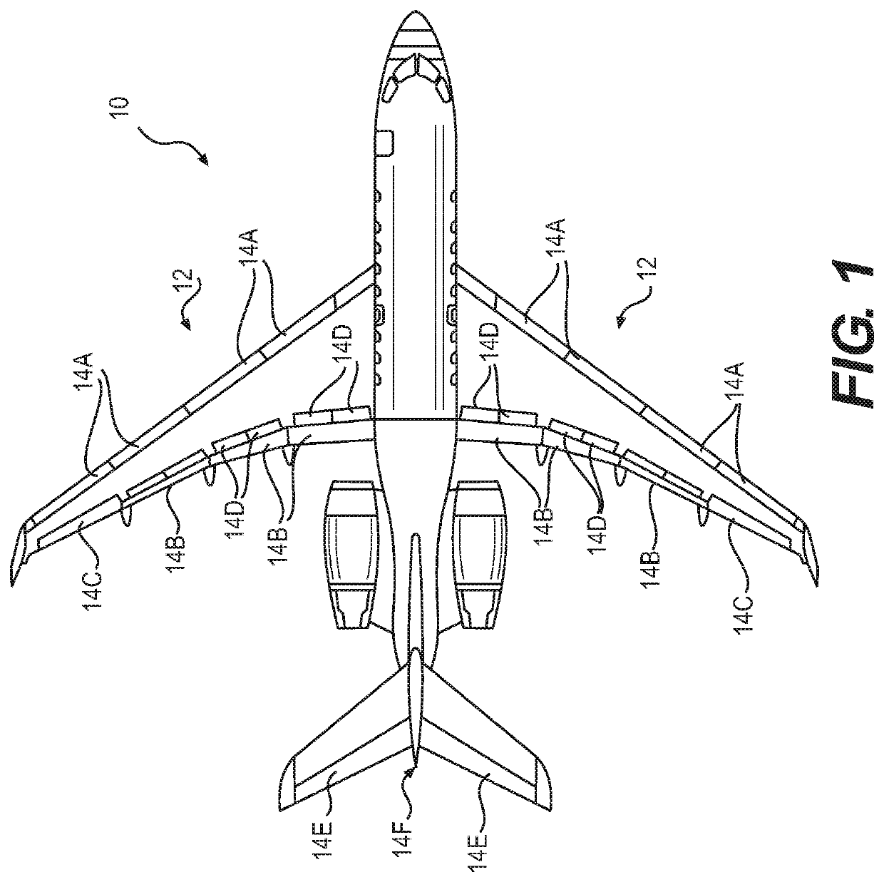
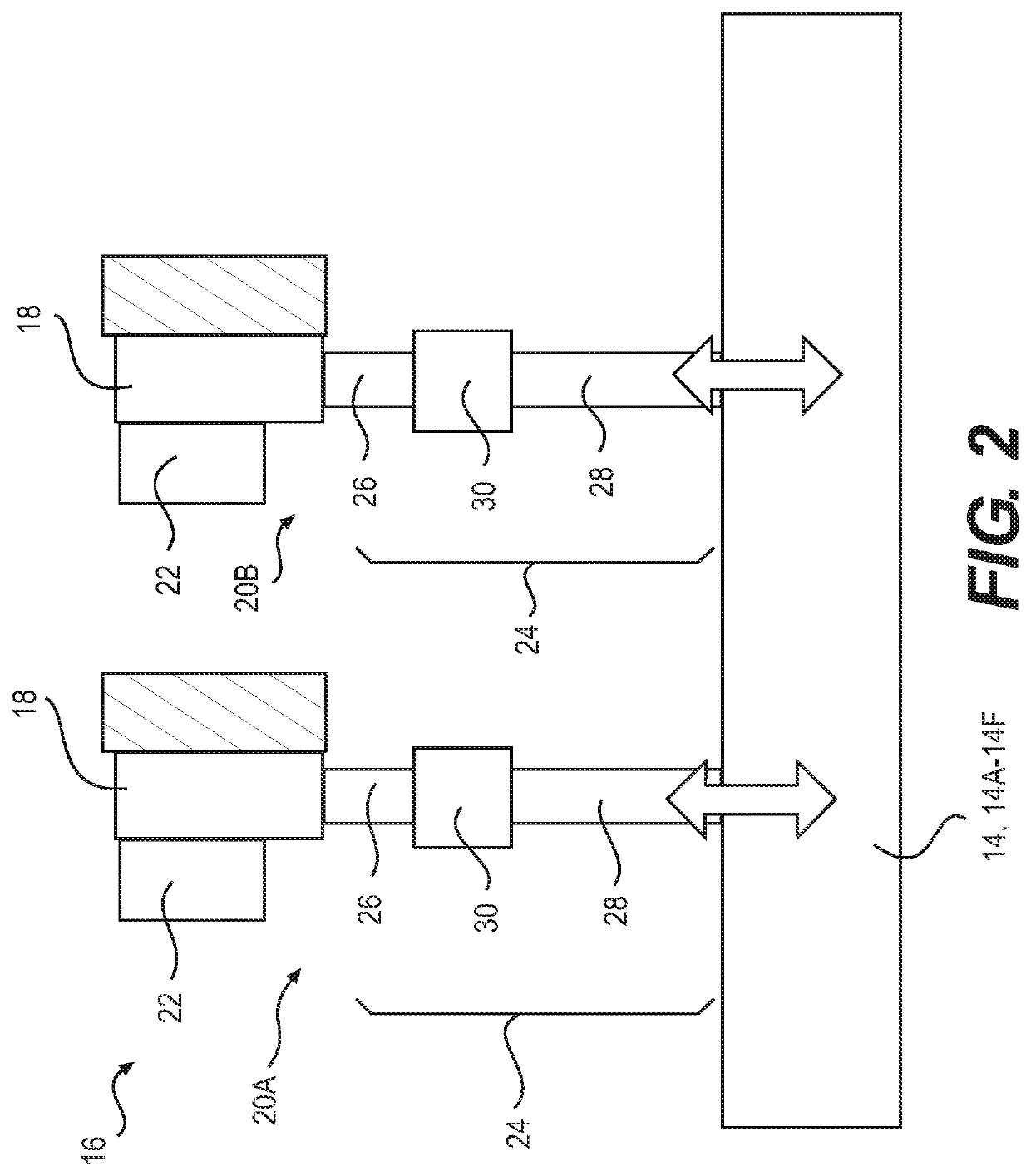
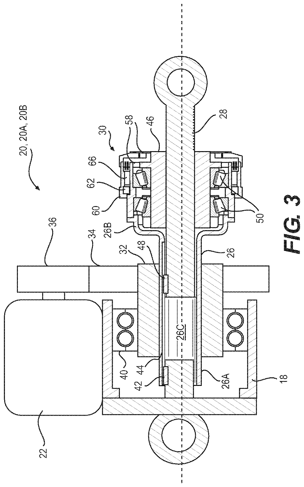
[0085]The present disclosure relates to the operation of flight control surfaces of aircraft. In various embodiments, the present disclosure describes systems, actuators, assemblies, components and methods useful in the operation of flight control surfaces of aircraft. The systems, actuators, assemblies, components and methods disclosed herein may, for example, be useful in maintaining at least partial control of a flight control surface during a jam or other fault condition(s) associated with an actuator of the flight control surface. In some embodiments, systems, actuators, assemblies, components and methods disclosed herein may be used in conjunction with primary flight control surfaces (e.g., ailerons, rudders, elevators and rotors) of fixed-wing or rotary wing aircraft. However, it is understood that aspects of the present disclosure may be used in conjunction with secondary or other types of f...


PUM


Abstract

Actuators and methods useful in the operation aircraft flight control surfaces are disclosed. Some of the actuators and methods disclosed may be useful in the operation flight control surfaces when a fault condition such as a jam associated with an actuator is detected. An exemplary electromechanical actuator disclosed comprises: a motor; a first screw configured for translation movement relative to a structure of the aircraft when driven by the motor; a second screw mounted in series with the first screw; and a fuse element coupling the first screw and the second screw together to permit translation movement of the second screw together with the first screw. The fuse element may permit at least partial disengagement of the second screw from the first screw to permit translation of the second screw relative to the first screw. The fuse element may also allow an active flutter damping of the flight control surface. The fuse element may comprise magneto-rheological fluid.

Description

CROSS-REFERENCE TO RELATED APPLICATION(S)[0001]This application is a national phase application under 35 U.S.C. 371 of International Patent Application No. PCT / IB2015 / 053536 filed on May 13, 2015, which claims priority from U.S. Provisional Patent Application Ser. No. 61 / 994,180, filed on May 16, 2014, the entire content of which is incorporated herein by reference.TECHNICAL FIELD[0002]The disclosure relates generally to the operation of aircraft flight control surfaces, and more particularly to actuators and methods useful for fault-tolerant operation and damping of aircraft flight control surfaces.BACKGROUND OF THE ART[0003]Aircraft typically comprise movable flight control surfaces that are deployed, retracted and / or deflected during operation of such aircraft. Primary control surfaces of fixed-wing aircraft are typically actuated using hydraulic actuators due to their relatively high reliability. Although electromechanical actuators (EMAs) have some operational advantages over h...

Claims


Application Information

Patent Timeline
Patent Type & Authority Patents(United States)
IPC IPC(8): F16H1/20F16H27/02F16H3/06F16H29/02F16H29/20B64C13/40F16H25/20F16H25/24
CPCF16H25/2056F16H25/20B64C13/40F16H25/205F16H25/2454F16H2025/2071F16H2025/2081B64C13/28B64C13/42
Inventor NFONGUEM, GUSTAVECHOUINARD, PATRICKPLANTE, JEAN-SÉBASTIENDENNINGER, MARCILIESCU, VLAD
Owner BOMBARDIER INC
Why Eureka
Try Eureka