Satellite with cylindrical main body, stack comprising such a satellite and launch assembly for such a satellite

a satellite and cylindrical technology, applied in the field of satellites, can solve the problems of increasing the weight of the launcher, limiting the number of satellites capable of being installed, and affecting the stability of the satellite, so as to facilitate the mounting of external items and increase the rigidity of the assembly

Active Publication Date: 2020-06-23
AIRBUS DEFENCE & SPACE
View PDF25 Cites 12 Cited by
  • Summary
  • Abstract
  • Description
  • Claims
  • Application Information

AI Technical Summary

Benefits of technology

[0026]The main body can then rest directly on, and be directly attached to, an interface ring of a launcher, without the intermediary of an adapter. The assembly thus formed creates a load transmission path between the interface ring and the body that is substantially parallel to the main axis of the main body, increasing the rigidity of the assembly.
[0027]According to an embodiment, the outer wall of the main body comprises at least one portion of plane surface, forming a facet, on which the external item of equipment is fixed. The facet facilitates mounting of the external item of equipment.

Problems solved by technology

The problems to be solved are, in particular, holding the satellites in the launcher and storing them in the nosecone.
In fact, during the launch, then at the time of release, the satellites are subjected to impacts and vibrations transmitted from the launcher to the satellites.
However, such a structure is bulky and is only suitable for satellites of small dimensions, or limits the number of satellites capable of being installed in the launcher due to the size of the nosecone.
Moreover, it constitutes an increase in the weight of the launcher, while being unnecessary for the mission.
A drawback of the structure is that it has a significant diameter compared to the standard launcher interface diameters in the space field.

Method used


Image

  • Satellite with cylindrical main body, stack comprising such a satellite and launch assembly for such a satellite
  • Satellite with cylindrical main body, stack comprising such a satellite and launch assembly for such a satellite
  • Satellite with cylindrical main body, stack comprising such a satellite and launch assembly for such a satellite

Examples


Embodiment Construction

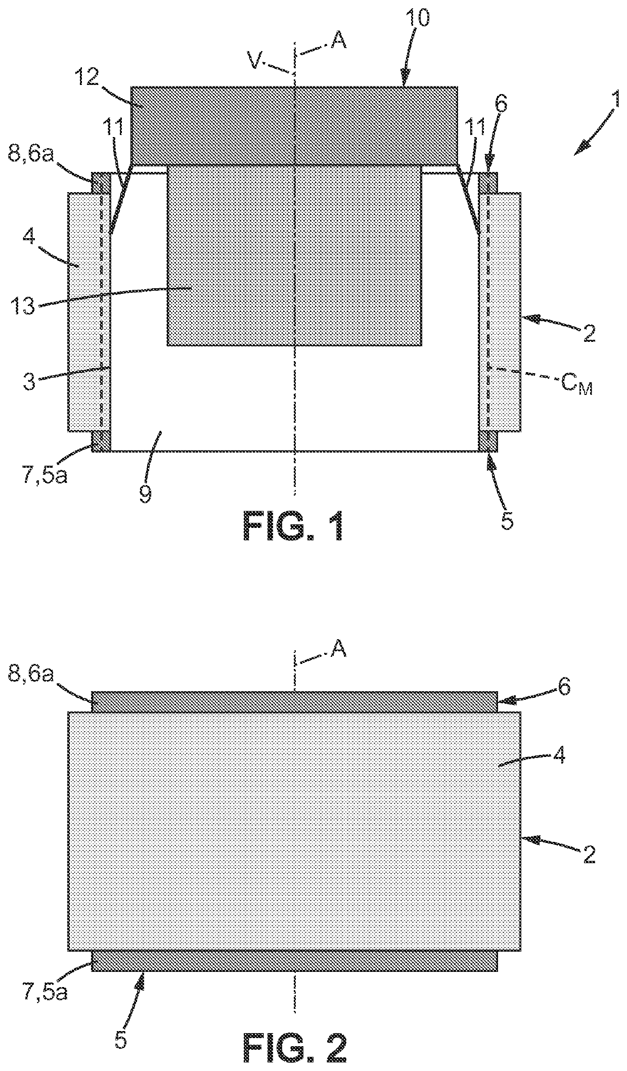
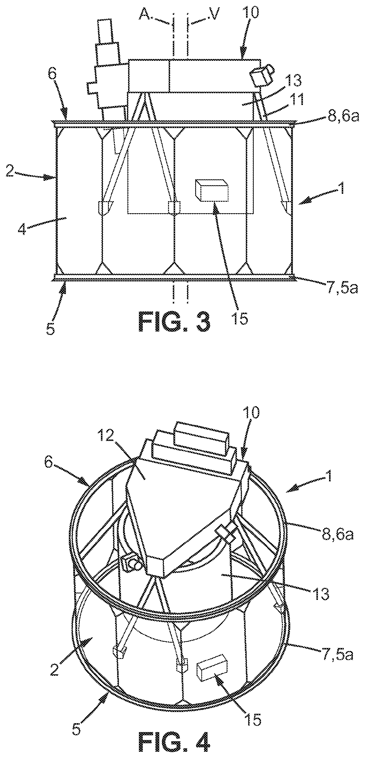
[0046]FIG. 1 diagrammatically represents a satellite 1, intended for being placed in orbit around the Earth by means of a launcher. The satellite 1 comprises a main body 2, having a generally cylindrical shape extending along a main axis A.

[0047]Hereinafter, the adjective “longitudinal” and its variants denote that which is parallel to the main axis A; the adjective “transversal” and its variants denote that which is comprised in a plane perpendicular to the main axis A.

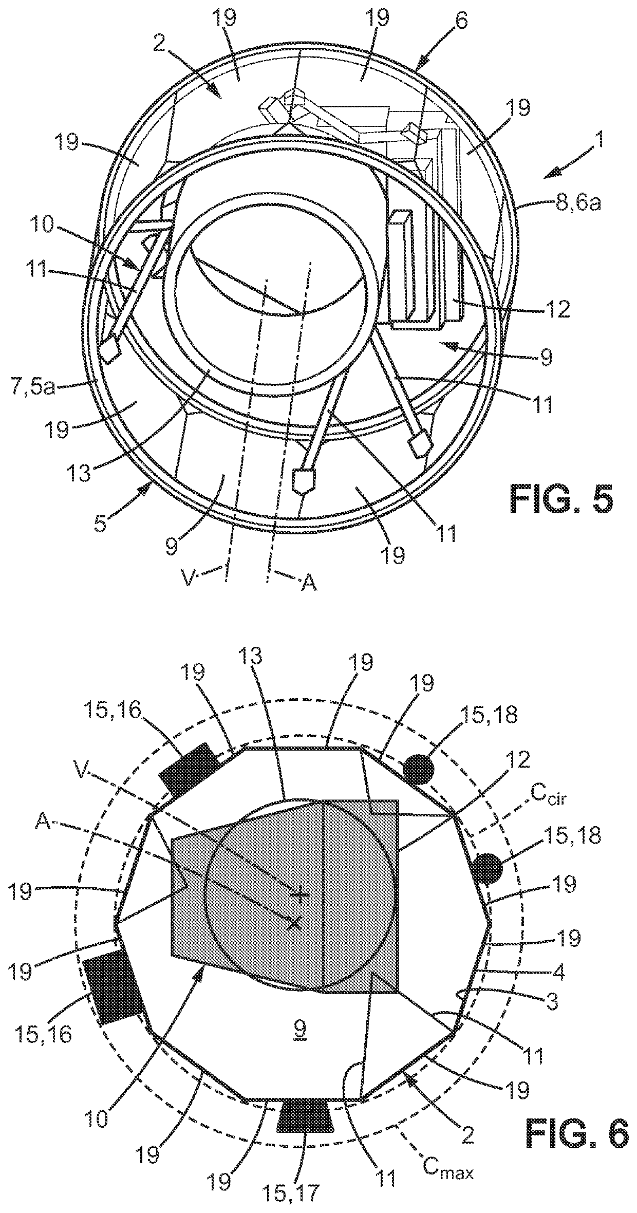
[0048]The adjective “cylindrical” must be understood herein in its broadest sense as defining a surface delineated by a generatrix line describing a directing curve. The directing curve can be circular, the main body 2 then having a tubular or polygonal shape, the main body 2 then having the shape of a prism.

[0049]The main body 2 has an inner wall 3 and an outer wall 4, which define a thickness of the main body 2.

[0050]Hereinafter, the adjective “inner” and its variants denote that which is turned towards or close to...


PUM


Abstract

Disclosed is a satellite including a cylindrical main body, the main body having an inner wall defining an inner space and an outer wall, and extending along a main axis between a lower end surface and an upper end surface, at least one of the lower end surface and the upper end surface including an interface mechanism intended for engaging with a complementary interface mechanism of another satellite or of a launcher, the satellite also including at least one external device attached to the outer wall of the main body, the outer device extending to project transversely from the outer wall relative to the main axis.

Description

BACKGROUND OF THE INVENTION[0001]Field of the Invention[0002]The invention relates to the field of space vehicles, and more particularly the field of satellites intended for placing into orbit.[0003]Description of the Related Art[0004]A satellite conventionally comprises a body forming a support for the items of equipment of the satellite. The items of equipment can be divided into two categories. The first category is called the payload and comprises the main instrument of the mission as well as the electronic devices necessary for its correct operation. It is for example an optical instrument, in the case of a mission intended for collecting images and optical measurements, or one or more antennas in the case of telecommunication satellites. The second category comprises items of equipment denoted in the present application as secondary, intended for the general operation of the satellite such as thrusters, receiving antennas, tanks or solar panels as well as electronic devices en...

Claims


Application Information

Patent Timeline
Patent Type & Authority Patents(United States)
IPC IPC(8): B64G1/64B64G1/10B64G1/26B64G1/28
CPCB64G1/1021B64G1/10B64G1/641B64G1/26B64G1/286B64G1/285B64G2001/643B64G2001/1028B64G1/1028B64G1/643
Inventor CHEYNET DE BEAUPRE, RENÉPALAYRET, FRANCISBERTHEUX, PHILIPPE
Owner AIRBUS DEFENCE & SPACE
Why Eureka
Try Eureka