
Display device

a display panel and display technology, applied in the field of display devices, can solve problems such as bad influence on the beauty of a product, and achieve the effects of preventing foreign matter infiltration and damage to the display panel, increasing bonding force, and increasing rigidity of the back cover

Active Publication Date: 2020-06-23
LG DISPLAY CO LTD
View PDF14 Cites 3 Cited by
  • Summary
  • Abstract
  • Description
  • Claims
  • Application Information

AI Technical Summary

Benefits of technology

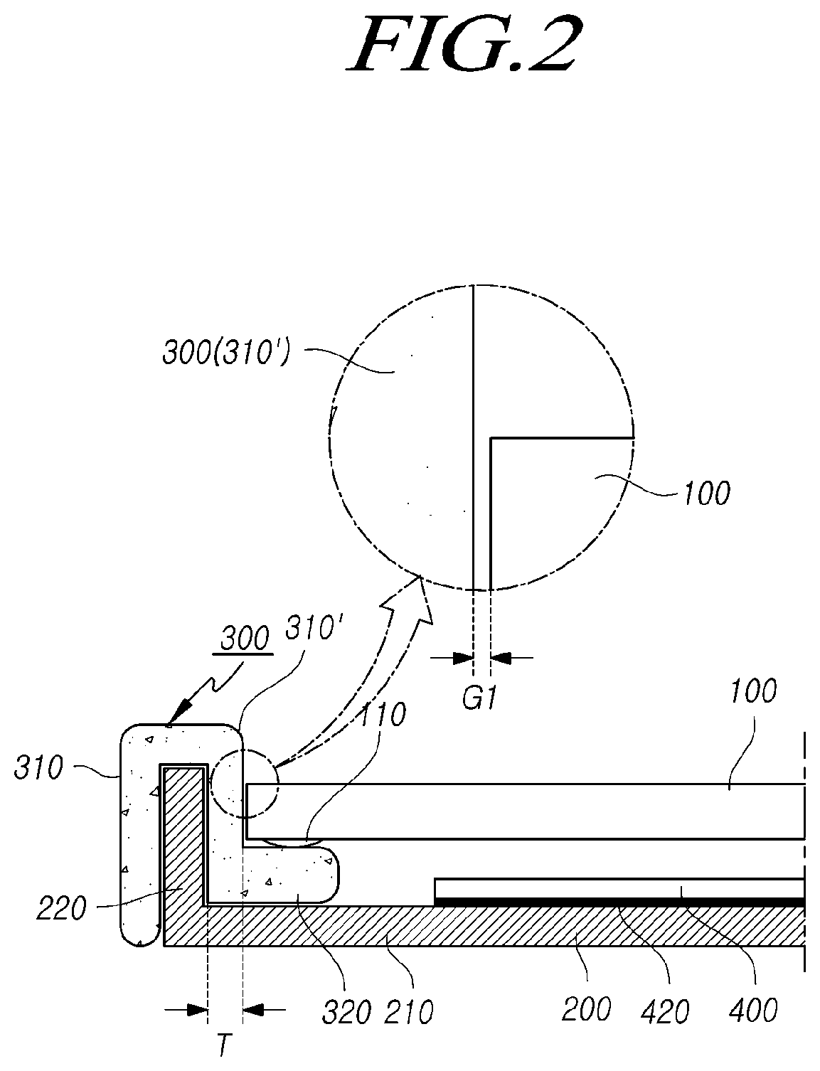
[0016]Accordingly, the present disclosure has been made in order to solve the above-described problems in the related art, and an object of the present disclosure is to provide a display device in which a back cover, which is a support structure constituting the display device, is formed in a bent structure, and a molding part made of an elastic material is formed to enclose a vertical extension portion, so that it is possible to prevent infiltration of foreign matter and the damage of the display panel which are caused due to a gap between the display panel and the support structure.
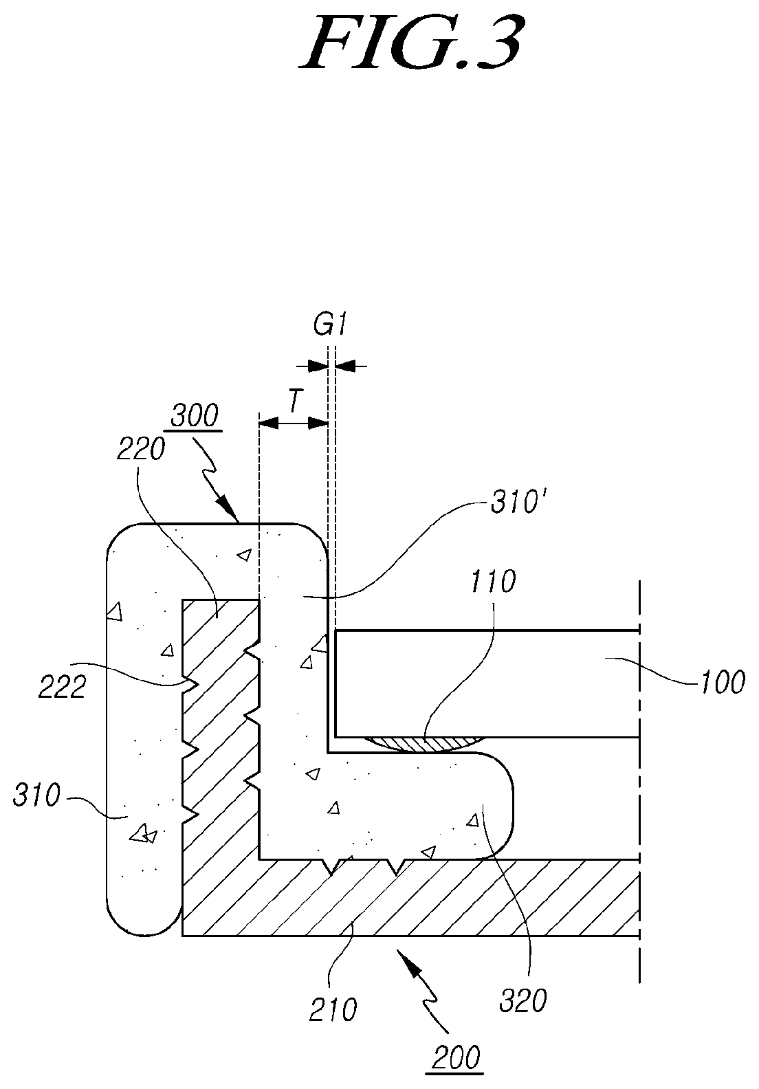
[0017]Another aspect of the present disclosure is to provide a display device in which a vertical extension portion is formed on a back cover which is a back support structure of the display device, and an elastic material molding part is formed to enclose the vertical extension portion in a state in which an uneven portion or a through hole is formed in the vertical extension portion, so that the bonding force between the back cover and the molding part can be increased.

Problems solved by technology

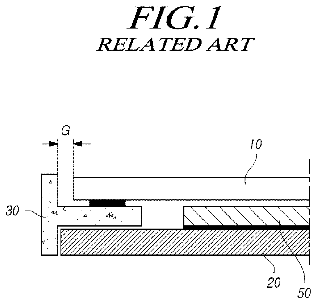
However, foreign matter or moisture may infiltrate into the display device through the border gap between the display panel and the support structure that supports the side surfaces of the display panel, which may cause a defect.
Such a gap is exposed to the external appearance of the display device, which also has a bad influence on the beauty of a product.

Method used


Image

  • Display device
  • Display device
  • Display device

Examples


Embodiment Construction

[0039]Hereinafter, some aspects of the present disclosure will be described in detail with reference to the accompanying illustrative drawings. In designating elements of the drawings by reference numerals, the same elements will be designated by the same reference numerals although they are shown in different drawings. Further, in the following description of the present disclosure, a detailed description of known functions and configurations incorporated herein will be omitted when it may make the subject matter of the present disclosure rather unclear.

[0040]In addition, terms, such as first, second, A, B, (a), (b) or the like may be used herein when describing components of the present disclosure. Each of these terminologies is not used to define an essence, order or sequence of a corresponding component but used merely to distinguish the corresponding component from other component(s). In the case that it is described that a certain structural element “is connected to”, “is coup...


PUM

PropertyMeasurementUnit
Shore Hardness A Indenteraaaaaaaaaa
thicknessaaaaaaaaaa
thicknessaaaaaaaaaa

Abstract

Disclosed aspects relate to a display device. By forming a back cover, which is the support structure constituting the display device, in a bent structure and forming a molding part made of an elastic material to enclose the vertical extension portion, a border gap, which is a clearance between the side surfaces of the display panel and the side surface support structure, can be minimized to maintain an excellent external appearance of the display device, and to prevent infiltration of foreign matter and damage of the display panel, which may be caused by the gap between the display panel and the support structure. By disposing a metal inner plate on the inner surface of the horizontal portion of the back cover, the rigidity of the back cover can be increased, the thickness of the back cover can be decreased, and heat generated from the display panel and the like can be smoothly dissipated.

Description

CROSS REFERENCE TO RELATED APPLICATION[0001]This application claims priority from Korean Patent Application No. 10-2016-0066452, filed on May 30, 2016, which is hereby incorporated by reference for all purposes as if fully set forth herein.BACKGROUNDField of the Disclosure[0002]The present disclosure relates to a display device, and, more particularly, to a display device that includes a back cover, which is a back support structure of the display device and a molding part formed of an elastic material which surrounds a vertical extension portion of the back cover, so that the infiltration of foreign matter, damage of a display panel, and the like, which may be caused due to a gap between the display panel and the support structure, can be prevented.Description of the Background[0003]As mobile electronic devices, such as mobile communication terminals and notebook computers, have been developed, there is an increasing demand for flat panel display devices applicable thereto.[0004]As...

Claims


Application Information

Patent Timeline
Patent Type & Authority Patents(United States)
IPC IPC(8): G06F1/16G02F1/01H01L27/32G02F1/1333H01L51/52
CPCG06F1/1637G02F1/0102H01L51/5243H01L51/5246H01L51/529H01L51/5253G06F1/1601H01L27/3213G02F1/133308H01L51/5281H10K50/80H10K50/84H10K59/351H10K50/8423H10K50/8426H10K50/86H10K50/87H10K50/844H05K5/03H10K59/1213H10K50/841H10K2102/3035H10K2102/351
Inventor KIM, DONGHOONCHOI, WONSEOKKANG, TAECHEOL
Owner LG DISPLAY CO LTD
Learn More