Composite comprising CNT fibres and an ionic conducting compound as part of an energy storage device

a technology of ionic conducting compound and energy storage device, which is applied in the direction of carbon nanotubes, filled nanotubes, inorganic chemistry, etc., can solve the problems of limiting the capacitance of the device and therefore the device performance in power and energy densities, reducing the mechanical properties of the electrode, and cumbersome cited procedures

Active Publication Date: 2020-06-23
BE AEROSPACE SYST
View PDF5 Cites 0 Cited by
  • Summary
  • Abstract
  • Description
  • Claims
  • Application Information

AI Technical Summary

Benefits of technology

[0026]As laminate composite structure enables easy integration into structural parts by incorporation as an interleaf, additional lamina or surface layer.
[0027]Comprising a solid polyelectrolyte and thus avoiding the need for a liquid electrolyte which are often volatile and toxic and imply that a heavy containment housing needs to be added to the device.
[0091]Several of those electrochemical capacitors may be easily connected in series, parallel or mix series / parallel in order to obtain a stack comprised of single cells providing the appropriate voltage and current required for each envisaged application. The electrochemical capacitors of the present invention are tough units, and as such are capable of functioning structural elements in a variety of constructions. The electrochemical capacitors may be configured in a variety of shapes what makes them easily to be integrated with different elements. For instance, the electrochemical capacitor of the present invention may be designed to be integrated in a protective casing or housing for a piece of equipment.

Problems solved by technology

These devices have the properties of rapid charging / discharging, however, are bulky and often heavy structures that take up a large space where they are finally used.
Nevertheless the main disadvantages of these supercapacitors are the very low specific surface of the carbon fibre (0.2 m2 / g), which limits their capacitance and therefore device performance in terms of power and energy densities.
Cited procedures are cumbersome and mechanical properties of electrodes are reduced.
Furthermore, the main disadvantage relates to the poor adhesion between CF and the CNTs.

Method used


Image

  • Composite comprising CNT fibres and an ionic conducting compound as part of an energy storage device
  • Composite comprising CNT fibres and an ionic conducting compound as part of an energy storage device
  • Composite comprising CNT fibres and an ionic conducting compound as part of an energy storage device

Examples


example 1

ization of the CNT Fibers and the Laminate Composite of the Invention

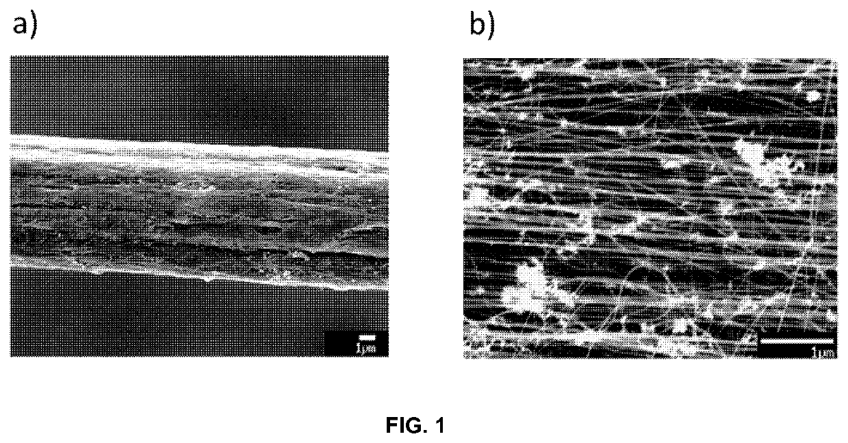
[0097]FIG. 1 presents an example of the fibre, which is a continuous macrosocopic filament. Because it is comprised of CNTs it has a high porosity (a) and a surface are of around 200 m2 / g, that is, about 1000 times higher than CF. This material is also strong and has proven to be easily integrated in composites to produce very strong and light structures.

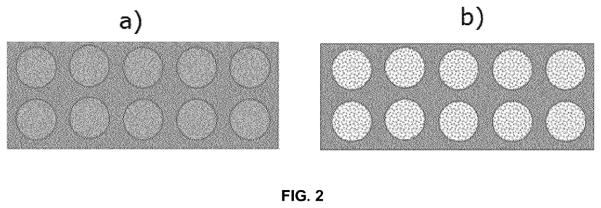
[0098]FIG. 2 presents a schematic comparison of the cross-sections of a CF composite and a porous CNT fibre composite (present invention), respectively. The much larger specific surface of the CNT fibre results in a better charge storage system. A comparison of standard electrochemical tests of these materials give a specific capacitance of about 0.5-3F / g for CF and around 40F / g for the CNT fibres.

[0099]This porosity not only increases overall charge storage performance, but also helps solve one of the main challenges in structural supercapacitors: simultaneous cha...

example 2

l Electrochemical Capacitor by Solution Impregnation Method and Ionic Polymer

[0101]A structural electrochemical capacitor comprising two laminate composites composed of CNT fibers, being the active material, impregnated with one ionic conducting compound acting as electrolyte by using a solution impregnating method. The ionic conducting compound is a binary blend of an ionic polymer, in particular a polycation, and a salt that can be combined at different mass ratios. The ionic polymer is poly(diallyldimethylammonium) bis(trifluoromethanesulfonyl)imide (pDADMATFSI) and the salt is an ionic liquid named N-methyl-N-butylpyrrolidinium bis(trifluoromethanesulfonyl)imide, (PYR14TFSI). In the present example the ratio of polymer / salt is 40 / 60 in weight. This ratio was selected because it provided self-standing membranes with an optimum balance between mechanical stability and ionic conductivity (from 10−7 to 10−1 S / cm in the temperature range of −30° C. to 120° C.).

[0102]In this example C...

example 3

l Electrochemical Capacitor by Non-Solution Impregnation Method and Non-Ionic Polymer

[0109]A structural electrochemical capacitor comprising two laminate composites composed of CNT fibers, being the active material, impregnated with one ionic conducting compound acting as electrolyte by using a non-solution impregnation method. The ionic conducting compound is a binary blend of a non-ionic polymer and a salt that can be combined at different mass rations. The non-ionic polymer is poly(vinylidene fluoride) (average Mw ˜534,000,) and the salt is an ionic liquid named N-methyl-N-butylpyrrolidinium bis(trifluoromethanesulfonyl)imide, (PYR14TFSI). In the present example the ratio of polymer / salt is 40 / 60 in weight. The ratio was chosen due to possibility to obtain a self-standing membrane with an optimum balance between mechanical stability and ionic conductivity (from 10−7 to 10−1 S / cm in the temperature range of −30° C. to 120° C.).

[0110]In this example CNT fiber electrodes have circul...


PUM

PropertyMeasurementUnit
electrical conductivityaaaaaaaaaa
specific surface areaaaaaaaaaaa
aspect ratioaaaaaaaaaa

Abstract

The present invention relates to Composite comprising CNT fibres and an ionic conducting compound forming a homogeneous continuous phase or a two-phase bicontinuous structure and its process of obtainment by impregnation methods. Furthermore the invention relates to its use as part of an energy storage device such as an structural flexible electrochemical capacitor.

Description

[0001]The present invention relates to a composite comprising CNT fibres and an ionic conducting compound forming a homogeneous continuous phase or a two-phase bicontinuous structure and its process of obtainment by impregnation methods. Furthermore the invention relates to its use as part of an energy storage device such as a structural flexible electrochemical capacitor.STATE OF ART[0002]There is an ever increasing need for more efficient energy storage devices for transport, portable electronics and other sectors. Amongst these devices, supercapacitors, and particularly those based on an electric double-layer (ED supercapacitor), have been developed for applications requiring high power densities. A typical example of such an application is an energy recovery system in an automobile, where the kinetic energy recovered from braking needs to be rapidly stored in a few seconds, i.e. too fast for batteries and similar devices based on redox reactions.[0003]In a supercapacitor the ene...

Claims


Application Information

Patent Timeline
Patent Type & Authority Patents(United States)
IPC IPC(8): H01G11/36C01B32/178H01G11/56
CPCH01G11/56C01B32/178H01G11/36C01B2202/22Y02E60/13C01B2202/32C01B2202/10
Inventor VILATELA, JUAN JOSÉMARCILLA, REBECCAPALMA, JESÚSSENOKOS, EVGENYDEGENHARDT, DETLEVASHRAF, SHERIF
Owner BE AEROSPACE SYST
Why Eureka
Try Eureka