Fishing reel having tension nut retainer
a technology of tension nut and fishing reel, which is applied in fishing reels, applications, and other directions, can solve the problems of tension nut being easily separated from the nut mount and lost, tension nut being fully loosened, and often losing regardless of the intention of the user, so as to prevent separation and loss of tension nut, the effect of maximizing the torque of the spool and preventing the separation of the tension nu
- Summary
- Abstract
- Description
- Claims
- Application Information
AI Technical Summary
Benefits of technology
Problems solved by technology
Method used
Image

Examples
first embodiment
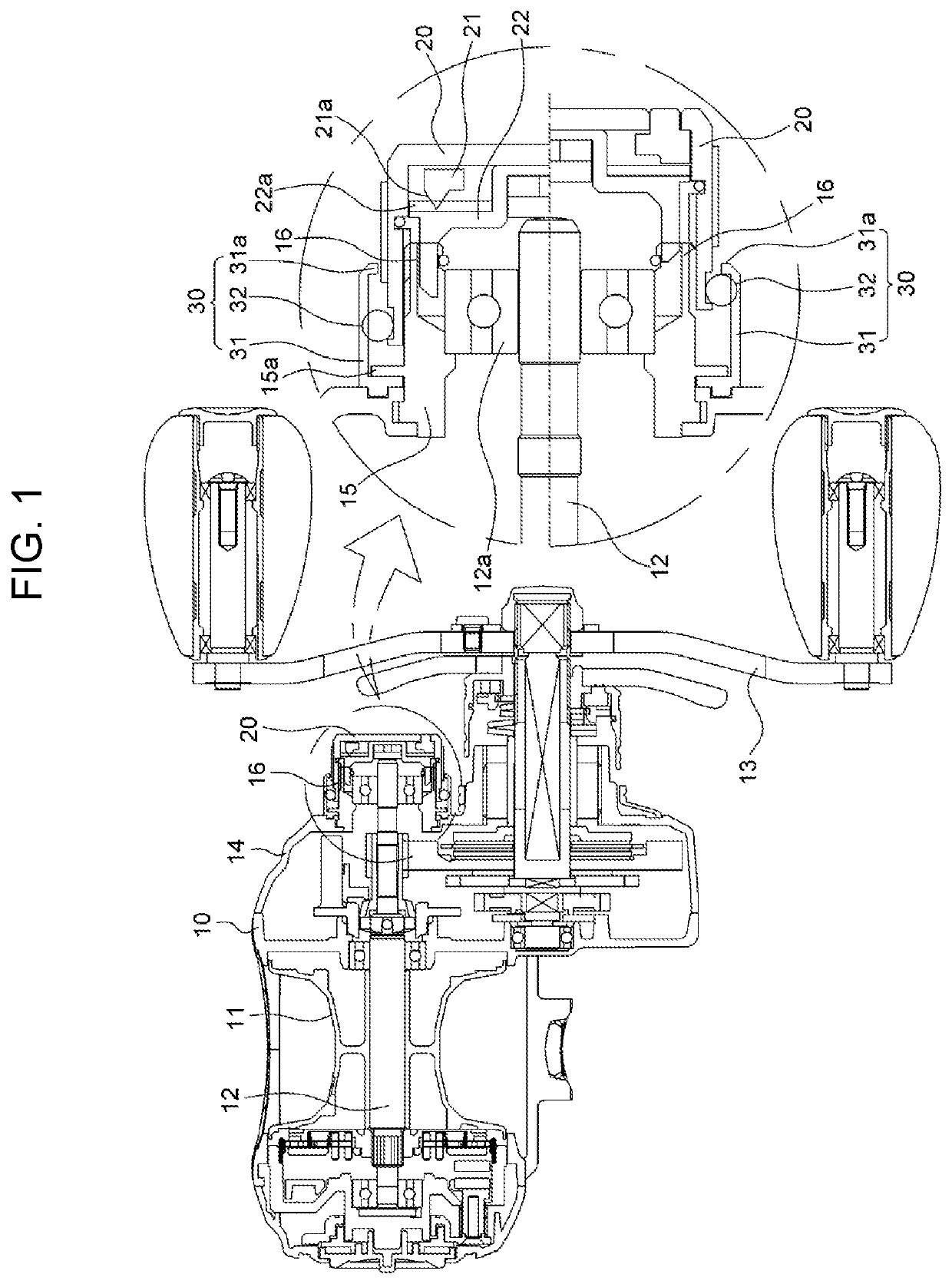
[0058]First, a first embodiment is described with reference to FIGS. 1 and 2A to 2D.
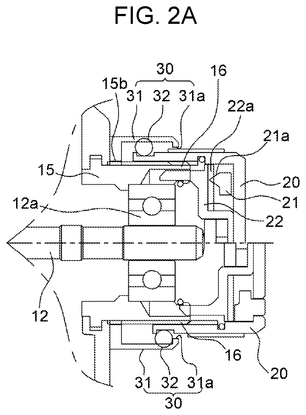
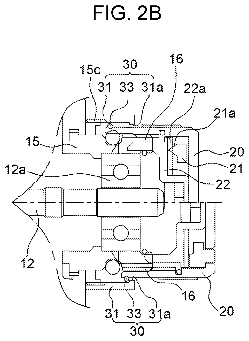
[0059]In the first embodiment, a retainer 30 according to the present invention includes: a cap 31 coupled to the frame 10 to cover the nut mount 16 to form a gap in which a second end of the tension nut 20 is inserted, and having a retaining step 31a protruding from the inner side; and a retaining portion formed on the outer side of the tension nut 20 and protruding from the retaining step 31a.
[0060]First, the cap 31 is disposed to cover the outer side of the metal 15 and the tension nut 20 is inserted in an insertion space between the metal 15 and the cap 31 and thread-fastened to the nut mount 16.
[0061]The retaining step 31a is bent inward at an end of the inner side of the cap 31.
[0062]The retaining portion is composed of retaining rings 32 and 33 that are O-ring or a C-ring and protrudes on the outer side of the tension nut 20 to be locked to the retaining step 31a.
[0063]Fitting grooves are fo...
second embodiment
[0094]Next, the present invention is described with reference to FIGS. 5, 6A, and 6B.
[0095]Before the second embodiment is described, as described above, a clicker is disposed in the tension nut 20 of the present invention.
[0096]The clicker includes a click spring 21 fixed by a click holder (not shown) in the tension nut 20 to be rotated with the tension nut 20 and an inner plate 22 moved with the tension nut 20 without rotating.
[0097]A projection 21a is formed on the inner side, which is in contact with the inner plate 22, of the click spring 21.
[0098]A prominence / depression portion 22a is circumferentially formed on the outer side, which the click spring 21 is in contact click spring 21, of the inner plate 22.
[0099]The projection 21a elastically comes in contact with the prominence / depression portion 22a.
[0100]When the click spring 21 is rotated with the tension nut 20, the projection 22a continuously hits against the prominence / depression portion 22a by elasticity, thereby gener...
third embodiment
[0112]Next, the present invention is described with reference to FIGS. 7 and 8.
[0113]As the third embodiment, the retainer 30 of the present invention is composed of a retaining ring 37 fitted on the outer side of the nut mount 16 and a locking step protruding inward from a second end of the tension nut 20 to be locked to the retaining ring 37.
[0114]That is, as shown in FIG. 10, an O-ring 24 is fitted on the nut mount 16 to secure waterproofness between the tension nut 20 and the metal 15.
[0115]As shown in FIGS. 7 and 8, the locking step 38 is formed on the inner side of the tension nut 20.
[0116]When the tension nut 20 is loosened to maximize the torque of the spool 11, the locking step 38 is locked to the retaining ring 37, so the tension nut 20 cannot be separated from the nut mount 16.
[0117]The retaining ring 37 shown in the right enlarged cross-sectional view of FIG. 7 has a retaining step 37a protruding outward at a first end such that the locking step 38 is locked to the retai...
PUM
 Abstract
Description
Claims
Application Information
 - Generate Ideas
- Intellectual Property
- Life Sciences
- Materials
- Tech Scout
- Unparalleled Data Quality
- Higher Quality Content
- 60% Fewer Hallucinations
Browse by: Latest US Patents, China's latest patents, Technical Efficacy Thesaurus, Application Domain, Technology Topic, Popular Technical Reports.
© 2025 PatSnap. All rights reserved.Legal|Privacy policy|Modern Slavery Act Transparency Statement|Sitemap|About US| Contact US: help@patsnap.com