Vehicle control method and control device
a control method and vehicle technology, applied in the direction of electrodynamic brake system, transportation and packaging, driver interaction, etc., can solve problems such as noise or vibration, and achieve the effect of reducing the torsional vibration of the drive shaft and suppressing the noise or vibration
- Summary
- Abstract
- Description
- Claims
- Application Information
AI Technical Summary
Benefits of technology
Problems solved by technology
Method used
Image
Examples
first embodiment
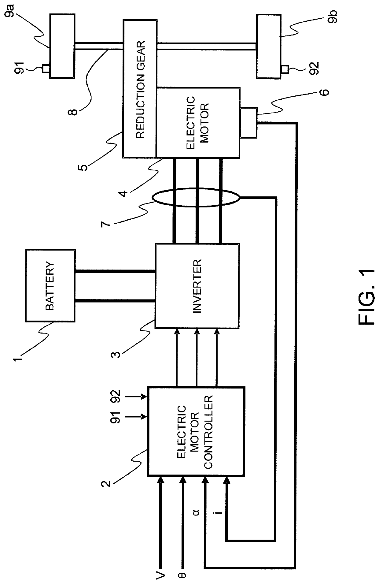
[0028]FIG. 1 is a block diagram illustrating major constituent components of an electric vehicle provided with a vehicle control device according to a first embodiment of the present invention.
[0029]The vehicle according to the present embodiment has an electric motor 4 connected to a drive shaft 8 of drive wheels 9a and 9b through a reduction gear 5, and decelerates by a regenerative braking force of the electric motor 4 under the control of an electric motor controller 2, which is the control device. Hereinafter, the reduction gear 5 and the drive shaft 8 up to the drive wheels 9a and 9b from the electric motor 4 will be referred to as the driving force transmission system.
[0030]The vehicle according to the present embodiment includes an electric vehicle that has electric power supplied from a battery 1, which is a power source, to the electric motor 4 through the intermediary of an inverter 3, and uses the power of the electric motor 4 generated by the electric power thereby to d...
second embodiment
[0173]FIG. 11 is a block diagram illustrating the functional configuration of a torsional angular velocity F / B calculator 30 in a second embodiment of the present invention.
[0174]The torsional angular velocity F / B calculator 30 of the present embodiment is provided with a max selector 38 in addition to the configuration of the torsional angular velocity F / B calculator illustrated in FIG. 10. The rest of the configuration is the same as the configuration illustrated in FIG. 10, so that like reference numerals will be assigned and the detailed description will be omitted.
[0175]The max selector 38 acquires a final torque command value Tmf* of a section other than a dead zone section from a torsion compensator 34 and a final torque command value Tmf* in the dead zone section from a torque limiter 35. Then, the max selector 38 selects the final torque command value Tmf* of the section other than the dead zone section or the final torque command value Tmf* in the dead zone section, whiche...
third embodiment
[0213]FIG. 16 is a block diagram illustrating an example of the functional configuration of a vibration damping control calculator 201 in a third embodiment of the present invention.
[0214]The vibration damping control calculator 201 corresponds to the vibration damping control calculator 200 in the first embodiment. The vibration damping control calculator 201 is provided with a torsional angular velocity F / F compensator 40, a difference F / B compensator 50, and an adder 60.
[0215]The torsional angular velocity F / F compensator 40 receives the desired torque command value Tmt* and outputs the final torque command value Tmf* and a motor rotational angular velocity estimated value ωm{circumflex over ( )} with respect to the final torque command value Tmf*.
[0216]The difference F / B compensator 50 receives the motor rotational angular velocity estimated value ωm{circumflex over ( )} and a motor rotational angular velocity detection value ωm, and outputs a difference torque compensation amou...
PUM
 Abstract
Description
Claims
Application Information
 - R&D
- Intellectual Property
- Life Sciences
- Materials
- Tech Scout
- Unparalleled Data Quality
- Higher Quality Content
- 60% Fewer Hallucinations
Browse by: Latest US Patents, China's latest patents, Technical Efficacy Thesaurus, Application Domain, Technology Topic, Popular Technical Reports.
© 2025 PatSnap. All rights reserved.Legal|Privacy policy|Modern Slavery Act Transparency Statement|Sitemap|About US| Contact US: help@patsnap.com


