Induction motor control apparatus and induction motor control method

a technology of induction motor and control apparatus, which is applied in the direction of electric generator control, dynamo-electric converter control, dynamo-electric gear control, etc., can solve the problem that the torsional vibration of the drive shaft cannot be suppressed

Active Publication Date: 2015-12-24
NISSAN MOTOR CO LTD
View PDF14 Cites 9 Cited by
  • Summary
  • Abstract
  • Description
  • Claims
  • Application Information

AI Technical Summary

Problems solved by technology

However, in the case of simply applying the vibration damping filter described in JP2001-45613A to a control system for

Method used


Image

  • Induction motor control apparatus and induction motor control method
  • Induction motor control apparatus and induction motor control method
  • Induction motor control apparatus and induction motor control method

Examples


first embodiment

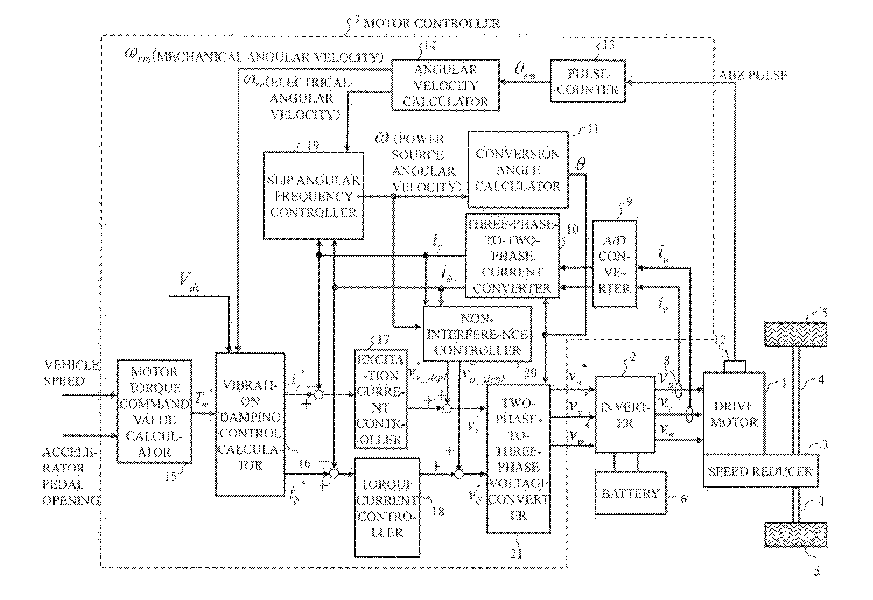
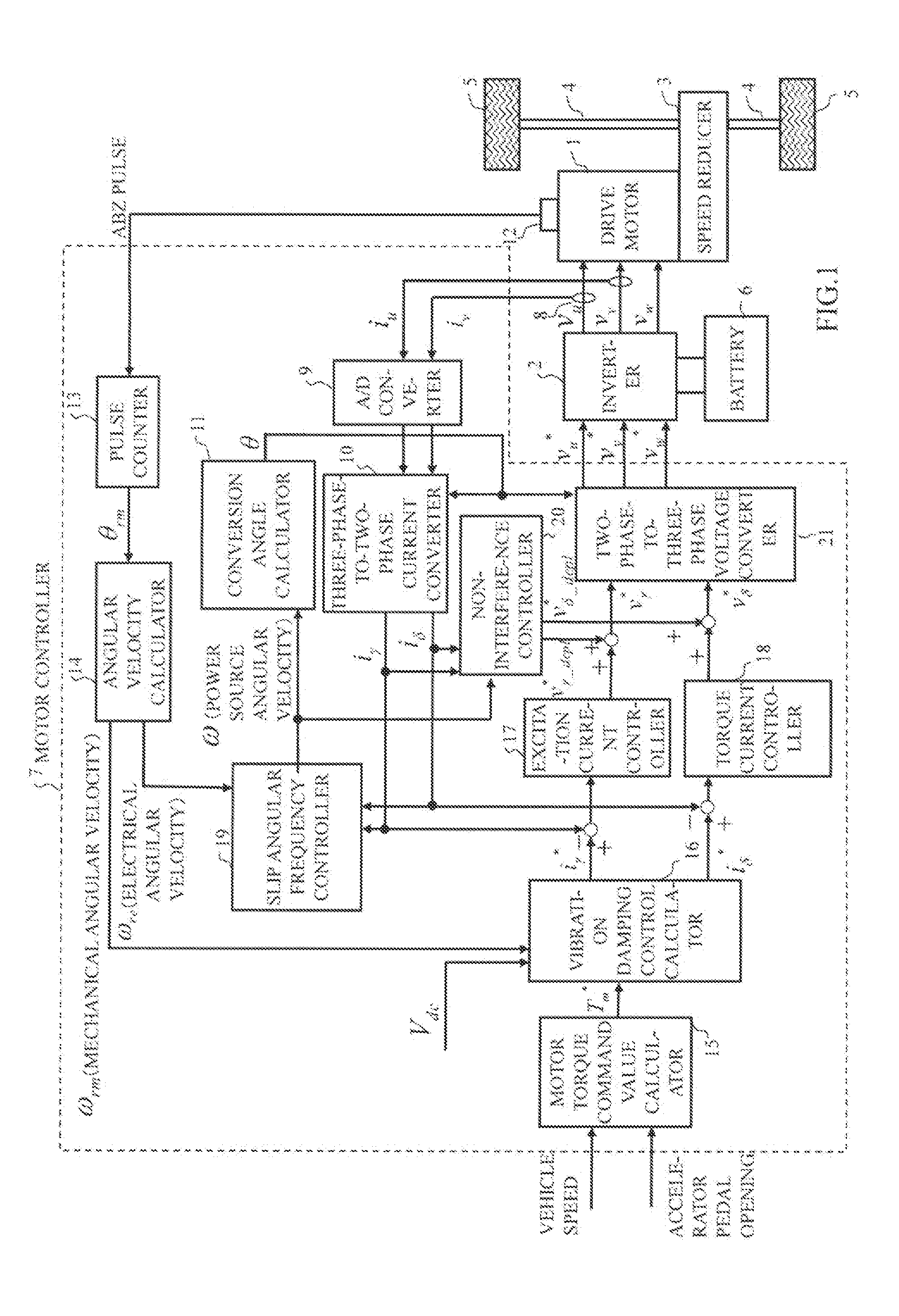
[0022]FIG. 1 is a block diagram showing a configuration of an induction motor control apparatus in a first embodiment. This induction motor control apparatus is, for example, applied to an electric vehicle. A configuration example applied to an electric vehicle is shown in FIG. 1. It should be noted that application to vehicles other than electric vehicles, such as hybrid vehicles and fuel cell vehicles, is also possible.

[0023]A motor controller 7 receives signals of various vehicle variables such as a vehicle speed, an accelerator pedal opening, a rotor position signal and a current flowing in a drive motor 1 in the form of digital signals as inputs. A motor controller 7 generates a PWM signal for controlling the drive motor 1 in accordance with various vehicle variables and generates a drive signal for an inverter 2 through a drive circuit in accordance with this PWM signal.

[0024]The inverter 2 includes two pairs of switching elements (power semiconductor elements such as IGBTs an...

second embodiment

[0081]When a current response is sufficiently faster than a rotor magnetic flux response, current response estimation / calculation processing performed in the magnetic flux estimator 23 can be omitted.

[0082]FIG. 8 is a block diagram showing a detailed configuration of a magnetic flux estimator 23 in a second embodiment. The magnetic flux estimator 23 of the second embodiment includes a magnetic flux response calculator 61 and a multiplier 62 and calculates a first torque command value T1* and a rotor magnetic flux estimated value φ̂ by the following equations (28), (29). KT denotes a coefficient determined by parameters of an induction motor and τφ denotes a time constant of a rotor magnetic flux response.

[Equation 28]

T1*=KT̂{circumflex over (φ)}·iδ1*

[Equation 29]

φ^=Mτφ*s+1·iγ1*(29)

[0083]As described above, also in an induction motor control apparatus in the second embodiment, the torsional vibration of a drive shaft of a vehicle can be suppressed without being affected by a rotor ma...

third embodiment

[0084]When an induction motor generates a torque in a state of zero rotor magnetic flux, a response delay of torque generation occurs due to a delay of a rotor magnetic flux response. In an induction motor control apparatus of a third embodiment, a fixed amount of the rotor magnetic flux is generated in advance before a motor torque command value is input.

[0085]FIG. 9 is a block diagram showing a detailed configuration of a magnetic flux estimator 23 in a third embodiment. The magnetic flux estimator 23 of the third embodiment includes a magnetic flux response calculator 71, a multiplier 72, a subtractor 73 and an adder 74 and calculates a first torque command value T1* and a rotor magnetic flux estimated valueφ̂ by the following equations (30), (31). KT denotes a coefficient determined by parameters of an induction motor and τφ denotes a time constant of a rotor magnetic flux response. Further, iγ1 . . . offset denotes a γ-axis current offset value input in advance.

[Equation 30]

T1*...


PUM


Abstract

An induction motor control apparatus controls an induction motor connected to drive wheels by setting a motor torque command value on the basis of vehicle information. The induction motor control apparatus calculates a first torque current command value and a first excitation current command value on the basis of the motor torque command value and estimates a rotor magnetic flux on the basis of the first excitation current command value. The induction motor control apparatus calculates a first torque command value on the basis of an estimated value of the rotor magnetic flux and the first torque current command value. Further the induction motor control apparatus calculates a second torque command value by applying filter processing to the first torque command value, a natural vibration frequency component of a drive shaft torque transmission system in a vehicle being removed in the filter processing. Then the induction motor control apparatus controls drive of the induction motor on the basis of the first excitation current command value and the second torque current command value.

Description

TECHNICAL FIELD[0001]The present invention relates to a control apparatus and a control method of an induction motor.BACKGROUND ART[0002]An induction motor vector control for controlling a motor torque by adjusting a magnetic flux current and a torque current obtained by converting a three-phase alternating current caused to flow into a stator of an induction motor into currents in an orthogonal two-axis coordinate system synchronized with a power source angular frequency (=motor electric angular frequency+slip angular frequency) is disclosed on pages 72-98 of “Actual Theory and Design of AC Servo Systems” by Hidehiko Sugimoto, Masato Koyama and Shinzo Tamai. In the case of controlling the slip angular frequency in proportion to a ratio of the torque current and a rotor magnetic flux, an induction motor torque is proportional to the product of the rotor magnetic flux generated with a delay in response to an excitation current and the orthogonal torque current.[0003]A vibration dampi...

Claims


Application Information

Patent Timeline
IPC IPC(8): H02P21/14
CPCB60L15/20Y02T10/7275B60L15/025H02P21/141B60L2240/14B60L2210/40B60L2220/12B60L2240/12B60L2240/421B60L2240/423B60L2240/427B60L2240/429B60L2240/529B60L2260/26B60L2240/80B60L2250/28B60L2260/24B60L2260/44B60L2270/145B60L2240/527B60L50/51Y02T10/7005Y02T10/7241Y02T10/643H02P21/05Y02T10/64Y02T10/72Y02T10/70
Inventor OONO, SHO
Owner NISSAN MOTOR CO LTD
Why Eureka
Try Eureka