Electrophotographic belt and image forming apparatus

a technology of image forming apparatus and electrotrophotography belt, which is applied in the direction of electrographic process apparatus, electrographic process, instruments, etc., can solve the problems of image quality degradation, and achieve the effect of preventing the transfer position of toner and excellent creep resistan

Active Publication Date: 2020-06-30
CANON KK
View PDF11 Cites 0 Cited by
  • Summary
  • Abstract
  • Description
  • Claims
  • Application Information

AI Technical Summary

Benefits of technology

[0006]An aspect of the present disclosure relates to providing an electrophotographic belt that is excellent in creep resistance and can prevent a transfer position of a toner from being shifted during secondary transfer.
[0007]Another aspect of the present disclosure is directed to providing an electrophotographic image forming apparatus capable of forming a high-quality electrophotographic image.

Problems solved by technology

That is, when a toner image carried on an outer peripheral surface of the electrophotographic belt is transferred onto paper (secondary transfer process), the transfer position of the toner on the recording medium deviates from the position that should be originally transferred, and the image quality deteriorates.

Method used


Image

  • Electrophotographic belt and image forming apparatus
  • Electrophotographic belt and image forming apparatus
  • Electrophotographic belt and image forming apparatus

Examples


example 1

[0106]A resin composition was prepared by hot-melt kneading in the mixing shown in Table 3 by using a twin screw kneading extruder (trade name: TEX30α; manufactured by Nippon Steel Works Co., Ltd.). The hot melt kneading temperature was adjusted to be in the range of 260° C. or higher and 280° C. or lower, and the hot melt kneading time was about 3 to 5 minutes. The obtained resin composition was pelletized and dried at a temperature of 140° C. for 6 hours.

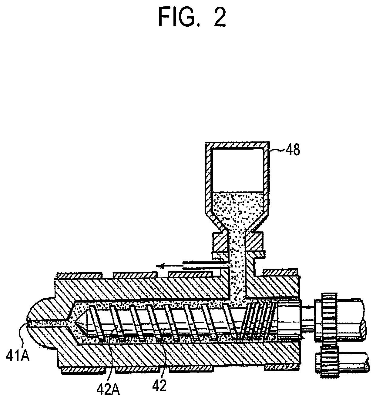
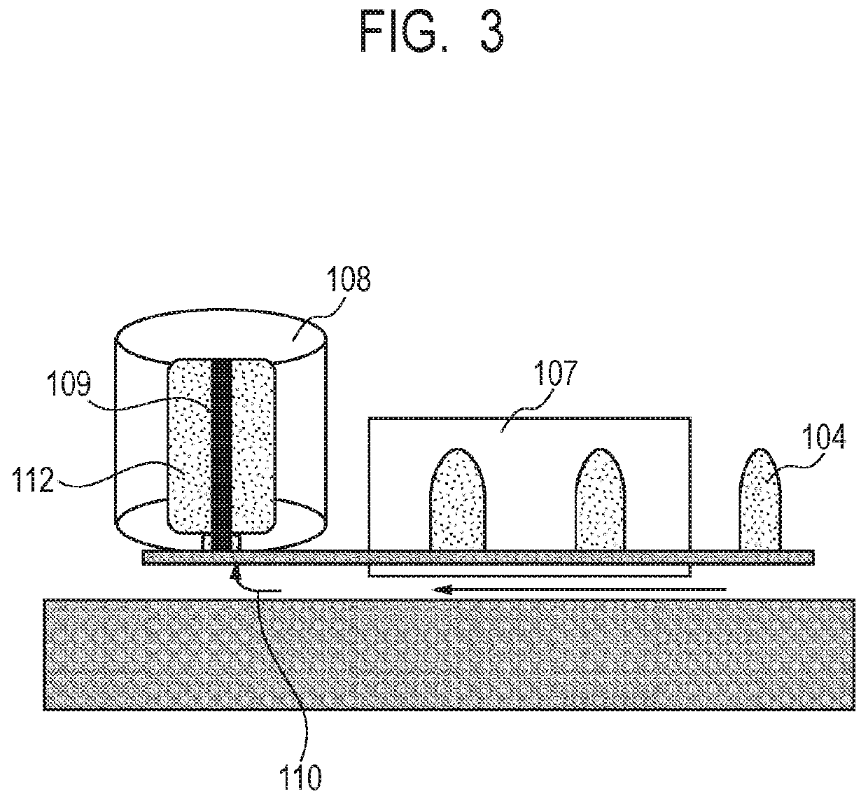
[0107]The dried pellet of the resin composition was put into a hopper 48 of an injection molding apparatus (SE180D, manufactured by Sumitomo Heavy Industries, Ltd.) having the configuration illustrated in FIG. 2. Then, a preform 104 having a height of 80 mm and a diameter of 50 mm was prepared by setting a set temperature of a cylinder to 290° C., being melted in screws 42 and 42A, and being injection-molded into a mold through a nozzle 41A. At this time, the injection molding temperature was 30° C. The preform 104 was put into a ...

examples 2 to 9

[0109]An electrophotographic endless belt was produced and evaluated in the same manner as in Example 1 except that the thermoplastic resin and the ionic electroconductive agent were mixed in the composition shown in Table 3.

Example 10

[0110]An electrophotographic endless belt was produced and evaluated in the same manner as in Example 1 except that the preform having a height of 88.5 mm and a diameter of 50 mm was produced. At this time, a stretch ratio of a blow bottle in a height direction was 4.52 times and the stretch ratio of the blow bottle in a radial direction was 4.52 times.

example 11

[0111]An electrophotographic endless belt was produced and evaluated in the same manner as in Example 1 except that the preform having a height of 70 mm and a diameter of 55 mm was produced. At this time, a stretch ratio of a blow bottle in a height direction was 5.71 times and the stretch ratio of the blow bottle in a radial direction was 4.11 times.


PUM

PropertyMeasurementUnit
diameteraaaaaaaaaa
diameteraaaaaaaaaa
diameteraaaaaaaaaa

Abstract

Provided is an electrophotographic belt having excellent creep resistance and digital reproducibility. The electrophotographic belt is composed of a biaxially stretched cylindrical film, and the film includes a matrix including a thermoplastic resin and an electroconductive domain including an ionic electroconductive agent, and when a surface resistivity of the film in a circumferential direction is defined as A, and a surface resistivity of the film in a direction orthogonal to the circumferential direction is defined as B, A≥B is satisfied, and a tensile modulus of elasticity of the film in the circumferential direction is 1.0 GPa or more and 3.0 GPa or less.

Description

BACKGROUND OF THE INVENTIONField of the Invention[0001]The present invention relates to an electrophotographic belt such as a conveyance transfer belt or an intermediate transfer belt used in an electrophotographic image forming apparatus and the like such as a copying machine or a printer, and also relates to an electrophotographic image forming apparatus provided with the electrophotographic belt.Description of the Related Art[0002]In an electrophotographic image forming apparatus, an endless-shaped electrophotographic belt made of a thermoplastic resin is used as a conveyance transfer belt for conveying a transfer material or an intermediate transfer belt. Such an electrophotographic belt is usually used while being stretched between rollers in the electrophotographic image forming apparatus, but may be deformed (hereinafter, also referred to as “creep”) due to long-term use.[0003]Japanese Patent Application Laid-Open No. 2007-24954 discloses a method for heating a preform made f...

Claims


Application Information

Patent Timeline
Patent Type & Authority Patents(United States)
IPC IPC(8): G03G15/20G03G15/16C08L77/12C08L67/02
CPCC08L77/12G03G15/1615C08L67/02G03G2215/1623G03G15/162G03G15/1635C08K5/19C08K5/43C08L77/00C08L69/00C08L77/06
Inventor UCHIDA, KOUICHI
Owner CANON KK
Why Eureka
Try Eureka