
Apparatus and method for passively cooling an interior

a technology for passive cooling and walls, applied in the direction of ducting arrangements, lighting and heating apparatuses, heating types, etc., can solve the problems of high building energy consumption, harmful environmental emissions associated with air conditioning, prior art wall assemblies are also susceptible to etc., to reduce mold and moisture damage, and structure durable

Active Publication Date: 2020-07-07
BROWN UNIVERSITY
View PDF69 Cites 0 Cited by
  • Summary
  • Abstract
  • Description
  • Claims
  • Application Information

AI Technical Summary

Benefits of technology

This solution reduces energy consumption, minimizes the use of harmful refrigerants, and effectively regulates temperature and humidity, thereby decreasing mold and moisture damage, while enhancing the durability and efficiency of cooling systems.

Problems solved by technology

The problems with high energy consumption of buildings and the harmful environmental emissions associated with air conditioning are well known.
Prior art wall assemblies are also susceptible to mold and moisture damage.

Method used


Image

  • Apparatus and method for passively cooling an interior
  • Apparatus and method for passively cooling an interior
  • Apparatus and method for passively cooling an interior

Examples


Embodiment Construction

[0033]The subject technology overcomes many of the prior art problems associated with cooling building interiors by using architectural membranes and membrane-based wall assemblies with nanoporous coatings. The advantages, and other features of the technology disclosed herein, will become more readily apparent to those having ordinary skill in the art from the following detailed description of certain preferred embodiments taken in conjunction with the drawings which set forth representative embodiments of the present disclosure and wherein like reference numerals identify similar structural elements. It is understood that references to the figures such as interior, exterior, up, down, upward, downward, left, and right are with respect to the figures and not meant in a limiting sense.

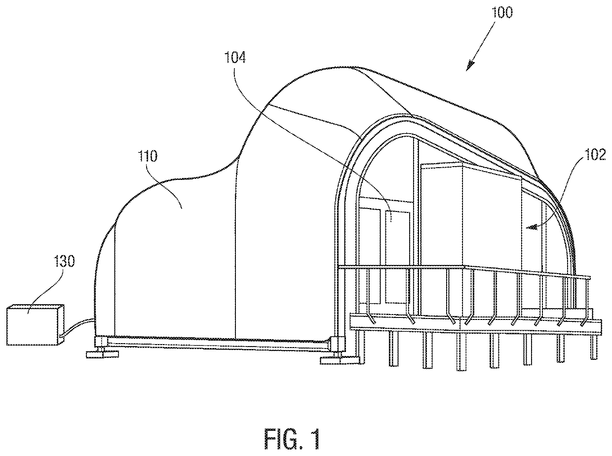
[0034]Referring now to FIG. 1, a house utilizing a system in accordance with one embodiment of the present disclosure is referred to generally by reference numeral 100. The house 100 includes an interio...


PUM

PropertyMeasurementUnit
lengthaaaaaaaaaa
thickaaaaaaaaaa
thickaaaaaaaaaa

Abstract

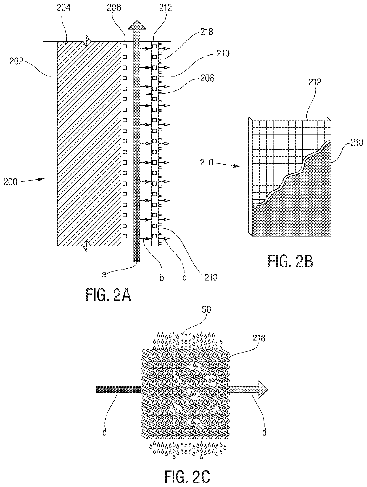
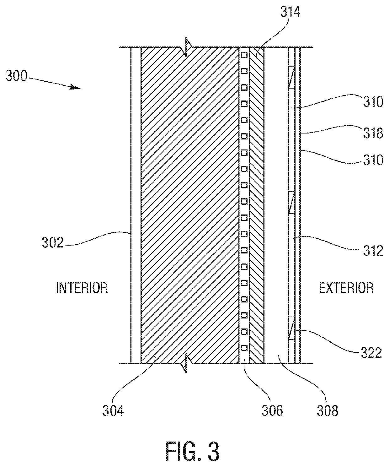
A system passively cools, regulates humidity and / or rectifies diffusive transport of water vapor in an interior area within a structure. The system includes a membrane assembly covering a portion of the structure, wherein the membrane has an interior side facing the interior area and an exterior side. The membrane assembly defines a plurality of pores. When cooling, a supply of fluid is provided to the membrane assembly so that capillary action of the pores redistributes the fluid to create evaporation and, in turn, the desired heat flow. The membrane assembly can include an architectural membrane coated with a porous matrix coating to form the pores. A pump can provide the fluid to the interior side of the membrane assembly. Preferably, the architectural membrane is woven PTFE-coated fiberglass and the porous matrix coating is titanium dioxide, zeolites and / or silica gel.

Description

CROSS-REFERENCE TO RELATED APPLICATION[0001]This application claims priority to U.S. Provisional Patent Application No. 62 / 300,288, filed Feb. 26, 2016, and is a continuation-in-part of U.S. Utility patent application Ser. No. 15 / 506,074, filed Feb. 23, 2017, which is a national stage application of Patent Cooperation Treaty Patent Application No. PCT / US2016 / 026408 filed Apr. 7, 2016, which claims the benefit of U.S. Provisional Patent Application No. 62 / 143,851, filed Apr. 7, 2015 and U.S. Provisional Patent Application No. 62 / 186,105, filed Jun. 29, 2015, each of which is incorporated herein by reference.BACKGROUND OF THE INVENTION[0002]1. Field of the Invention[0003]The subject disclosure relates to methods and systems for structure wall assemblies, and more particularly, to improved methods and systems for: passively cooling an interior area of a structure; passively regulating the temperature of an interior area; passively regulating the relative humidity of the interior area; ...

Claims


Application Information

Patent Timeline
Patent Type & Authority Patents(United States)
IPC IPC(8): E04C2/28E04B1/74F24F5/00F24F13/02
CPCF24F5/0035F24F13/0227E04B1/74E04C2/28F24F2221/17Y02B30/54F24F2003/1435F24F2005/0082F24F3/1411
Inventor STEIN, DEREK MARTIN
Owner BROWN UNIVERSITY
Learn More