Cutting unit and cutting process

a technology of cutting unit and cutting process, which is applied in the direction of meat processing devices, meat shaping/cutting, metal working apparatus, etc., can solve the problems of complex mechanical configuration and disadvantages of using them together with a stop plate which is used as a stop for the strand, and achieve the effect of improving the shape precision and weight precision of the cut off slices

Active Publication Date: 2020-07-14
TVI ENTWICKLUNG & PROD GMBH
View PDF18 Cites 2 Cited by
  • Summary
  • Abstract
  • Description
  • Claims
  • Application Information

AI Technical Summary

Benefits of technology

[0021]Thus it is an object of the invention to provide a cutting device with a blade and a stop plate which improves shape precision and weight precision of the cut off slices and to provide a method for operating device.Solution
[0023]The stop plate provides during applying and contact pressing the strand at the back side of the stop plate before beginning the cut off process that it is prevented over an entire face of the strand that the cross-sectional shape of the strand is increased by expansion through the axial contact pressure and on the other hand side that the plastically deformable material of the strand does not get squeezed out through the cutting gap between the blade and the contact plate during the cutoff process in an undesirable manner.
[0024]By the same token, the cut-off slice has to be able to slide easily through the cutting gap and have to be able to flip and drop without problems over the functional edge of the stop plate that is typically arranged at a slant angle at an end of the cutoff process.
[0025]Therefore, the radial distance between the cutting edge and the stop plate is increased according to the invention, in particular towards an end of the cutoff process so that the slice drops onto a drop surface, typically a conveyor belt, without distortions or bulges.

Problems solved by technology

However, using them together with a stop plate which is used as a stop for the strand is disadvantageous.
Thus this requires a complex mechanical configuration.

Method used


Image

  • Cutting unit and cutting process
  • Cutting unit and cutting process
  • Cutting unit and cutting process

Examples


first embodiment

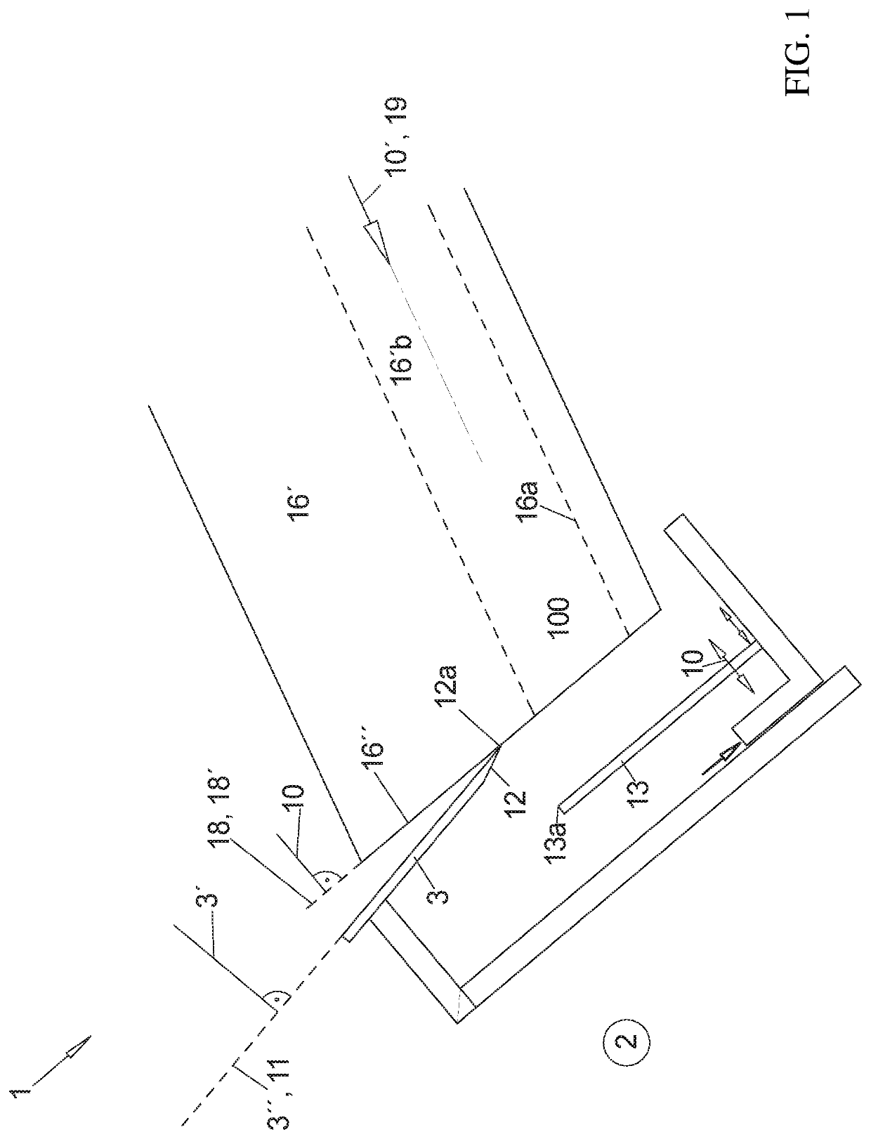
[0077]FIG. 1 illustrates a side view an analogy to the view of FIGS. 1A through 2D of a longitudinal cut through a form tube and a cutting unit 1, only in order to clarify the different layers of directions and planes that are being used.

[0078]The product strand 100 is moved onto a contact surface 16a advantageously in a form tube 16′ with a circumferentially closed cross-section in the feed direction 10′, which is typically the main extension direction of the product strand 100, wherein the feed direction 10′ is the direction towards the forward open end of the form tube 16′ where the blade 3 is arrange for cutting off the slices 101.

[0079]The blade 3 illustrated herein is a strip-shaped blade 3, which has a straight cutting edge 12a and which is driven to oscillate in the direction of this edge 12a in order to achieve the desired cutting effect.

[0080]The straight cutting edge 12 of the blade 3 that is ground advantageously only one side, namely on the side that is oriented away fr...

third embodiment

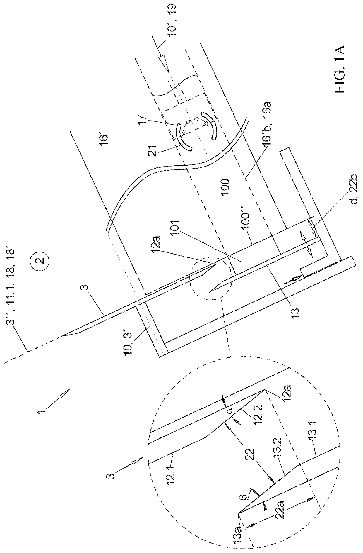
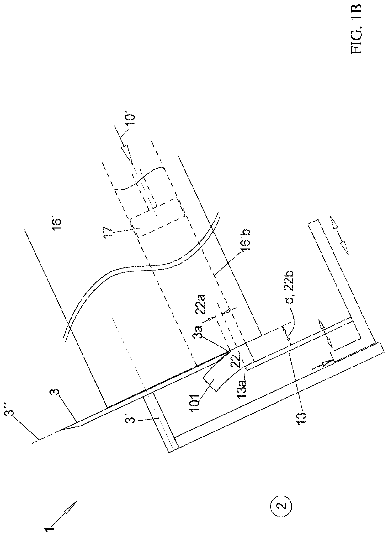
[0097]In FIGS. 2A-2D the stop plate 13 is adjustable in the axial direction 10 relative to the blade 3 not only before a beginning of cutting up the product strand in order to determine the thickness d of the slices 101 to be produced but also during each individual cutting process.

[0098]When the blade 3 and the stop plate 13 are attached at the cutting frame of the cutting unit 1 as illustrated the stop plate 13 shall be movably attached in a controlled manner in the direction 18 / 18′ at the cutting frame, also during the individual cutting processes not only before the cutting process begins. In the axial direction 10 the stop plate 13 is always adjustable relative to the cutting frame in order to predetermine a thickness d of a slice 101.

[0099]In FIGS. 1A through 2B the rotating blade 3 is attached in the cutting frame so that it is rotatable about its blade axis 3′ so that all blade movements besides the blade rotation are jointly performed by the cutting frame and the blade 3 as...


PUM


Abstract

A cutting unit to facilitate ejecting a slice that is cut off from a product strand a radial distance between a blade edge of the rotating blade. The functional edge of the stop plate may be adjusted during the cutting movement. In one embodiment, the functional edge of the stop plate may be adjusted at an end of the cutting movement.

Description

CROSS-REFERENCE TO RELATED APPLICATIONS[0001]This nonprovisional application claims the benefit of German Patent Application No. 102017112177.3 filed Jun. 2, 2017, the entire disclosure of which is incorporated herein by reference.FIELD OF THE INVENTION[0002]The invention relates to a cutting unit for cutting slices from a typically strand-shaped based product, thus a food strand like, e.g., a sausage strand or cheese strand, typically with a cross-section that is constant over a length of the strand or a fresh meat strand than typically with a cross-section that is variable over its length.[0003]Typically cut off slices shall be as close as possible to a particular target weight.BACKGROUND OF THE INVENTION[0004]Thus a blade is moved through a cross-section of the strand transversal to a longitudinal direction of the strand and thus a slice is cut off and the blade is moved back again in the transversal direction. Before cutting off the next slice, the strand is advanced in the long...

Claims


Application Information

Patent Timeline
Patent Type & Authority Patents(United States)
IPC IPC(8): B26D1/157B26D7/01B26D1/143B26D7/32B26D3/16B26D1/00A22C17/00B26D1/15B26D7/26
CPCA22C17/002B26D7/2635B26D1/15B26D1/157B26D7/01B26D7/32B26D1/0006B26D1/143B26D3/161B26D2210/02B26D2001/0053B26D2007/013
Inventor VÖLKL, THOMASMAYR, MARTIN
Owner TVI ENTWICKLUNG & PROD GMBH
Why Eureka
Try Eureka