
Mobile terminal

a mobile terminal and terminal technology, applied in the field of waterproof mobile terminals, can solve the problems of complex assembly and difficulty in securing an internal space, and achieve the effect of enhancing waterproof quality

Active Publication Date: 2020-07-21
LG ELECTRONICS INC
View PDF5 Cites 1 Cited by
  • Summary
  • Abstract
  • Description
  • Claims
  • Application Information

AI Technical Summary

Benefits of technology

[0006]Therefore, an aspect of the detailed description is to implement a simple waterproof structure.
[0008]In an embodiment, a portion of the side region is demarcated by a slit part and radiates in a specific frequency band, and a slit molding part protruding from the first molding region is inserted into the slit part, and thus, a radiation region does not have a possibility of being in contact with other regions of the metal case, enhancing radiation quality.
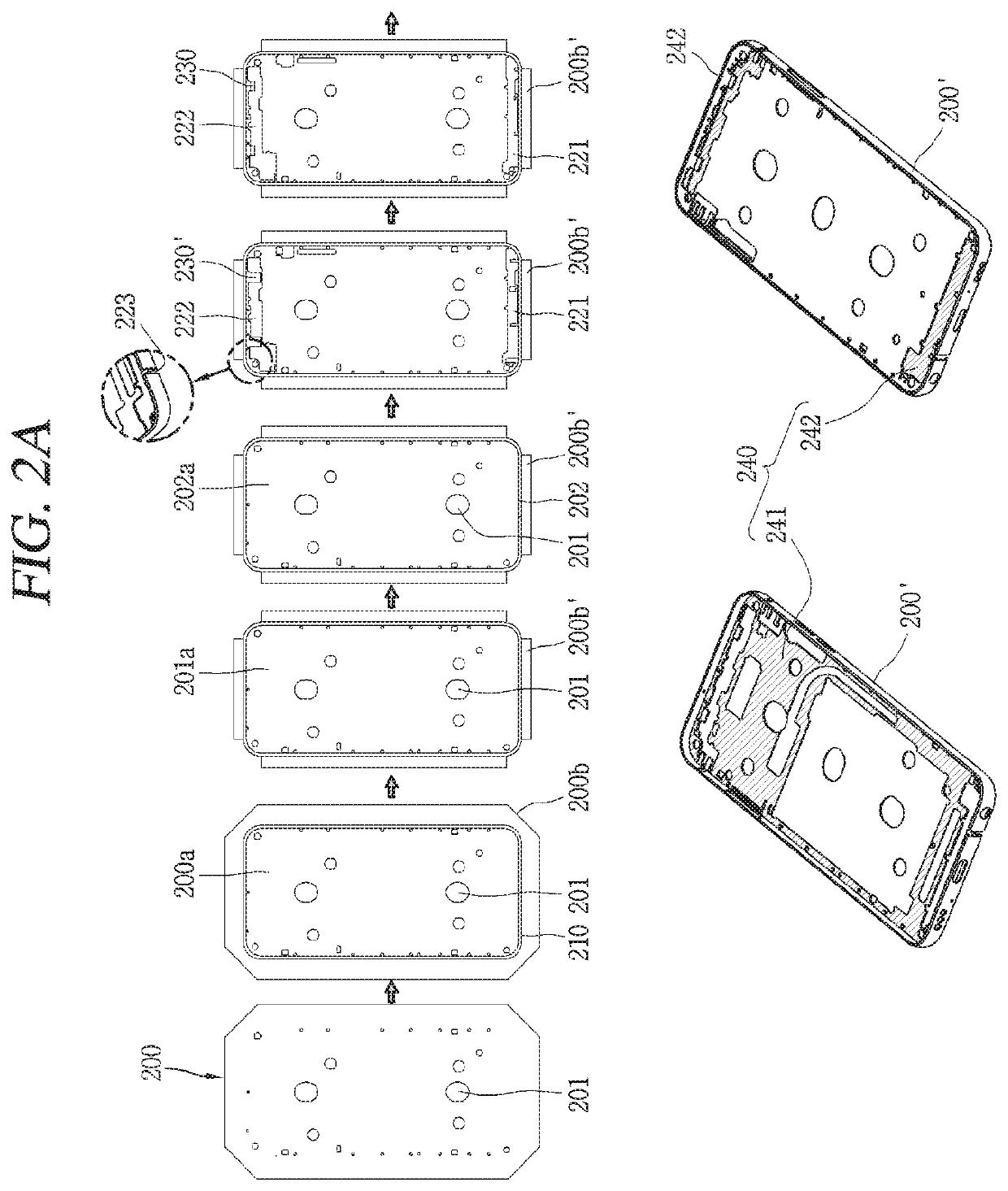
[0010]According to the present disclosure, since the front and rear molding parts are formed along an inner surface of a region forming a side surface of the terminal body and have a closed loop shape, a problem that a portion is separated in a state of being mounted in the metal case may be prevented.
[0011]Also, although water is introduced due to the slit formed in the metal case, water cannot escape from between the side region of the metal case and the first molding region of the rear molding part due to the closed loop shape of the first molding region. Thus, introduced water is prevented from being introduced to the inside of the terminal body, enhancing waterproof quality.

Problems solved by technology

As a waterproof type terminal has recently been developed, a hole formed outside the terminal and a waterproof structure for blocking flow of water introduced through an assembly structure are added, so that it is difficult to secure an internal space and assembly is complicated.

Method used


Image

  • Mobile terminal
  • Mobile terminal
  • Mobile terminal

Examples


Embodiment Construction

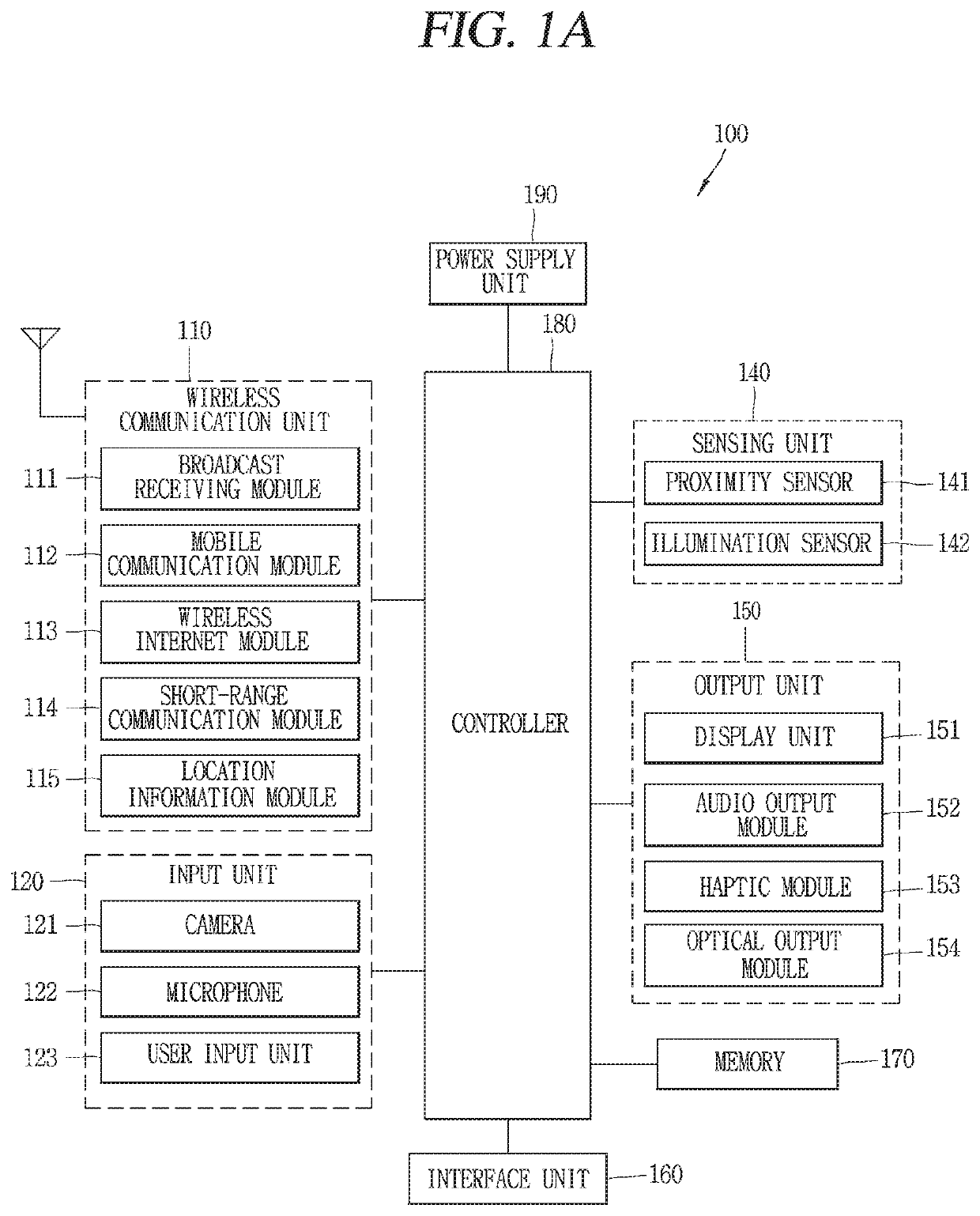
[0024]First, FIG. 1A is a block diagram illustrating a mobile terminal 100 related to the present disclosure.

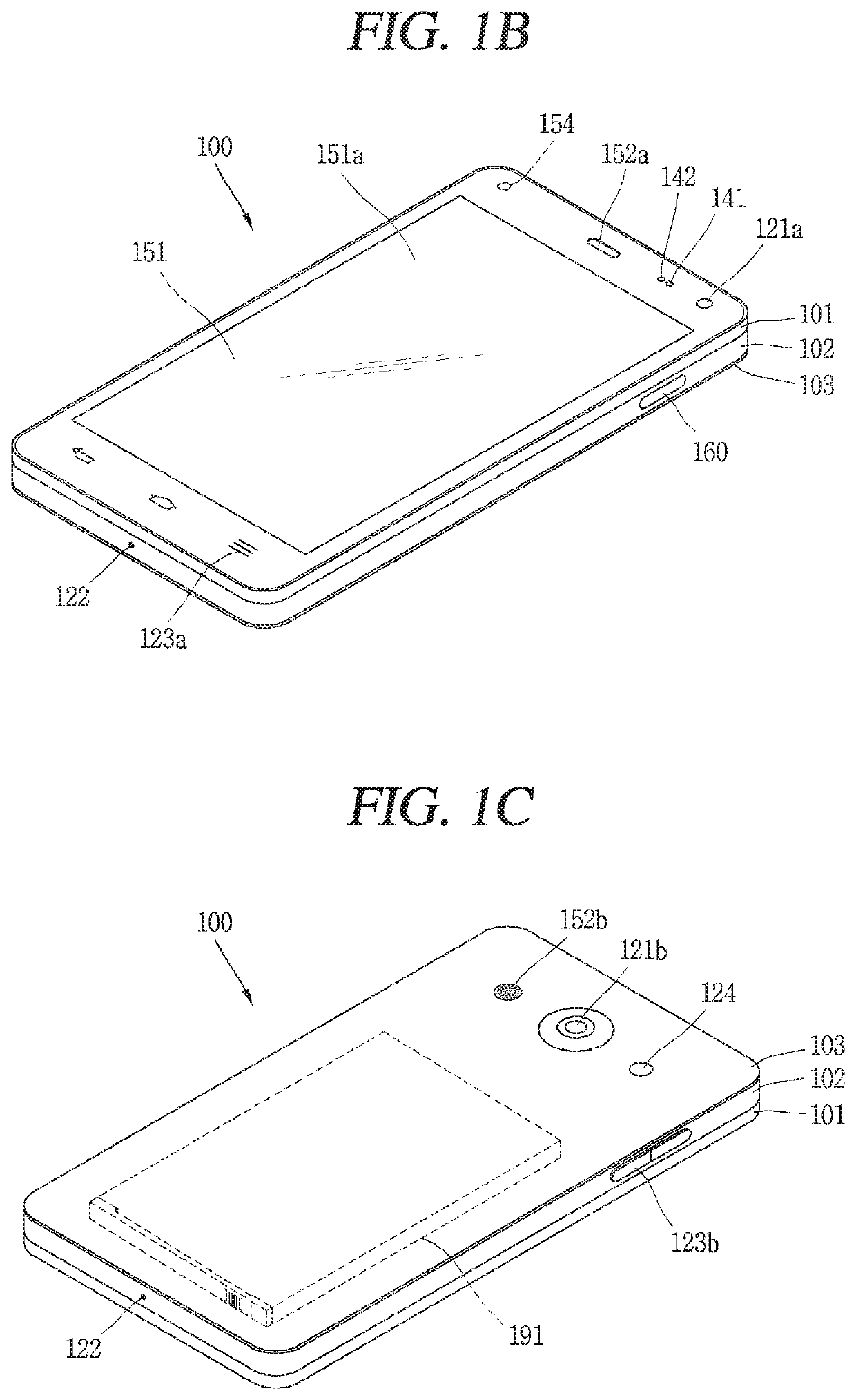
[0025]The mobile terminal 100 is shown having components such as a wireless communication unit 110, an input unit 120, a sensing unit 140, an output unit 150, an interface unit 160, a memory 170, a controller 180, and a power supply unit 190. It is understood that implementing all of the illustrated components is not a requirement, and that greater or fewer components may alternatively be implemented.

[0026]The wireless communication unit 110 typically includes one or more modules which permit communications such as wireless communications between the mobile terminal 100 and a wireless communication system, communications between the mobile terminal 100 and another mobile terminal, communications between the mobile terminal 100 and an external server.

[0027]Further, the wireless communication unit 110 typically includes one or more modules which connect the mobile terminal 100 ...


PUM


Abstract

A mobile terminal includes a terminal body, a metal case forming an appearance of the terminal body and including a side region and a second region integrally formed with the side region and supporting the inside of the terminal body, and a rear molding part formed in a region of the metal caser. The rear molding part includes a first molding region formed to have a closed loop shape along an inner surface of the side region and a second molding region extending from the first molding region and forming a receiving space for receiving at least one electronic component. The side region includes a plurality of opening holes, and the first molding region is formed to cover the plurality of opening holes.

Description

CROSS-REFERENCE TO RELATED APPLICATION[0001]Pursuant to 35 U.S.C. § 119(a), this application claims the benefit of earlier filing date and right of priority to Korean Patent Application No. 10-2017-0115315, filed on Sep. 8, 2017, the contents of which are hereby incorporated by reference herein in its entirety.BACKGROUND OF THE INVENTION1. Field of the Invention[0002]The present disclosure relates to a waterproof-type mobile terminal having a metal case2. Background of the Invention[0003]Mobile terminals may be generally classified as mobile / portable terminals or stationary terminals according to their mobility. Mobile terminals may also be classified as handheld terminals or vehicle mounted terminals according to whether or not a user may directly carry the terminal.[0004]Such terminals have various functions according to the development of technologies. For example, a terminal is implemented in the form of a multimedia device having a plurality of functions such as capturing an im...

Claims


Application Information

Patent Timeline
Patent Type & Authority Patents(United States)
IPC IPC(8): H04M1/00H04M1/02G06F1/16H01Q1/22H01Q1/24H01Q21/28H04B1/3888H01Q13/10H04M1/18H04B1/38H04M1/23
CPCH01Q1/2291H04M1/0202H01Q1/243G06F1/1656H04B1/3888H01Q21/28H01Q13/10H04M1/0266H04M1/236H04M1/18H04B2001/3894H04M1/0249H01Q7/00
Inventor SONG, INSULEE, JAEWOOKHONG, SUKHOKIM, JEONGJOONG
Owner LG ELECTRONICS INC
Learn More