
Device for the pressure-supported or pressure-controlled ventilation of a patient with reduced spontaneous breathing

a technology for reducing spontaneous breathing and ventilating patients, which is applied in the field of ventilating patients with reduced spontaneous breathing pressure supported or pressure controlled, can solve the problems of reducing spontaneous breathing, tidal volumes that hardly differ from one another, and presenting a burden on patients, etc., and achieves reduced spontaneous breathing, little effect, and simple design

Active Publication Date: 2020-08-04
DRAGERWERK AG
View PDF10 Cites 0 Cited by
  • Summary
  • Abstract
  • Description
  • Claims
  • Application Information

AI Technical Summary

Benefits of technology

This invention is about a device that helps ventilate patients who can't breathe well. The goal is to make the device flexible and quick to adjust to changes in the patient's breathing. The device should also be less affected by changes in the quality of the electromyography (EMG) signals that measure the patient's breathing. Additionally, the system should be simple and easy to integrate into existing ventilation systems.

Problems solved by technology

This may represent a burden for the patient.
It is often problematic, in case of pressure-supported ventilation, that, contrary to natural spontaneous breathing, tidal volumes that hardly differ from one another are obtained.
It is, furthermore, problematic in the prior-art systems for the pressure-supported or pressure-controlled ventilation of a patient with reduced spontaneous breathing that changes in the breathing activity of the patient are taken into account for the control of the ventilation system, especially of the ventilator unit, either only insufficiently or at least with a great time delay.
Another problem is often represented here by the fluctuating quality of the EMG signal, which is superimposed, on the one hand, by strong other electrical signals, for example, ECG signals, and is influenced, on the other hand, by the changing contacting of the electrodes on the thorax.

Method used


Image

  • Device for the pressure-supported or pressure-controlled ventilation of a patient with reduced spontaneous breathing
  • Device for the pressure-supported or pressure-controlled ventilation of a patient with reduced spontaneous breathing
  • Device for the pressure-supported or pressure-controlled ventilation of a patient with reduced spontaneous breathing

Examples


Embodiment Construction

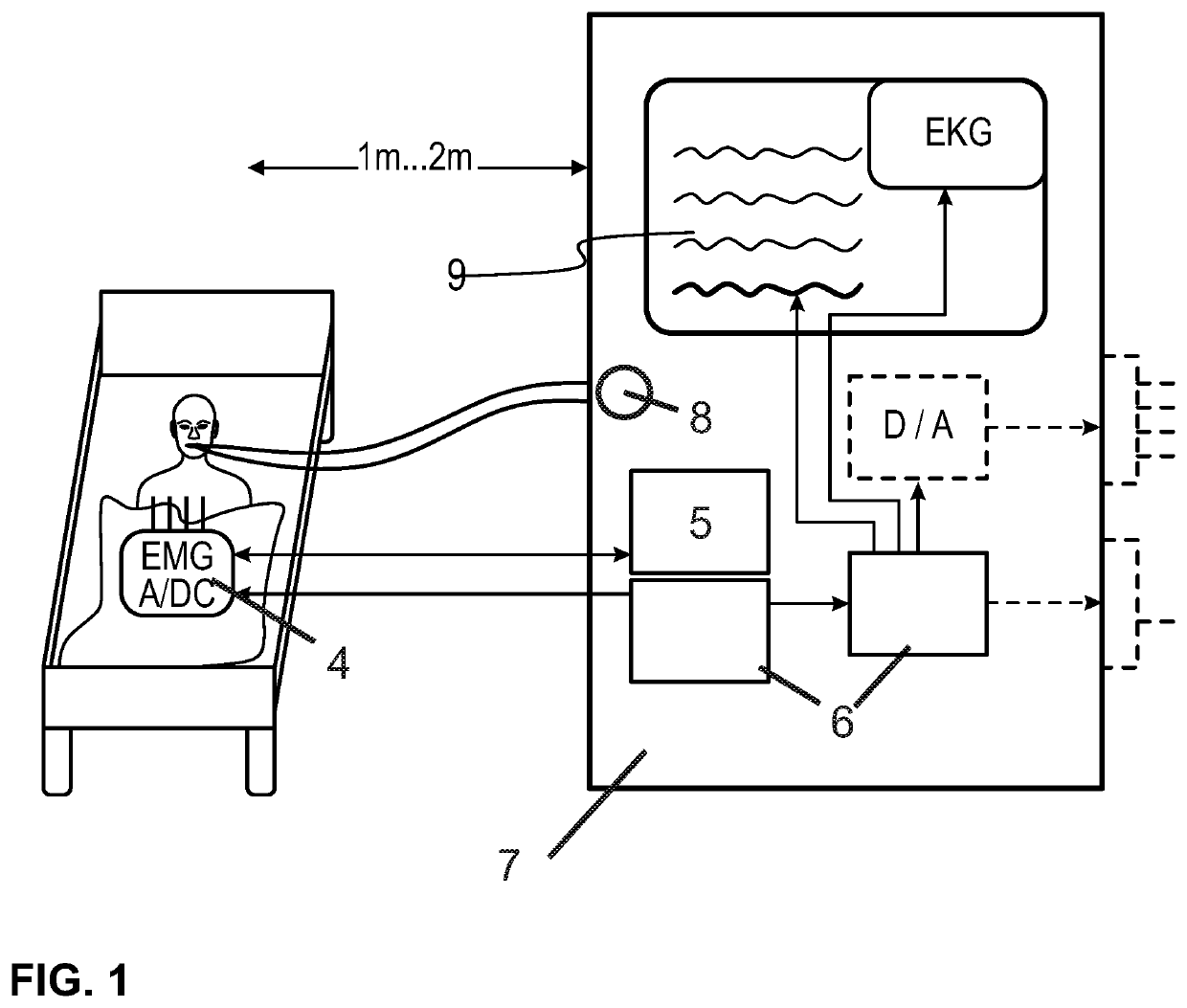
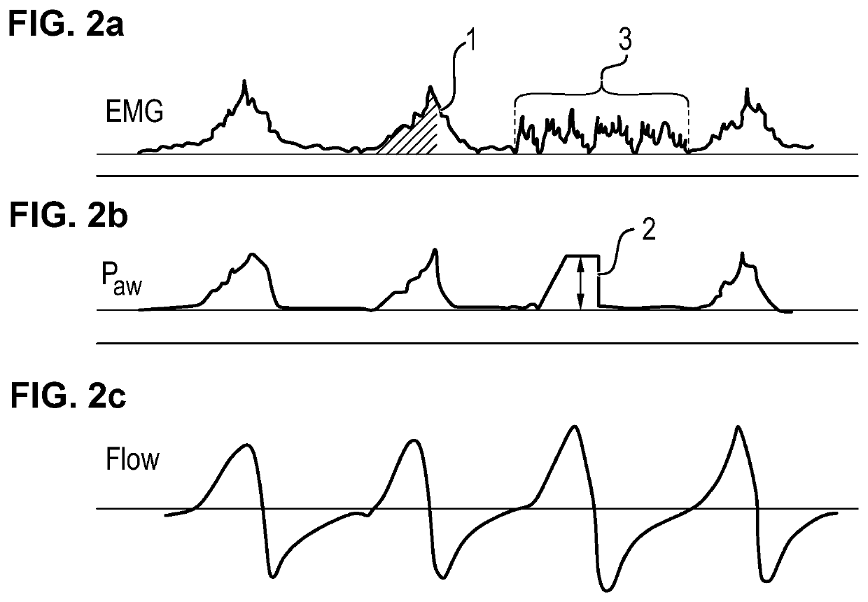
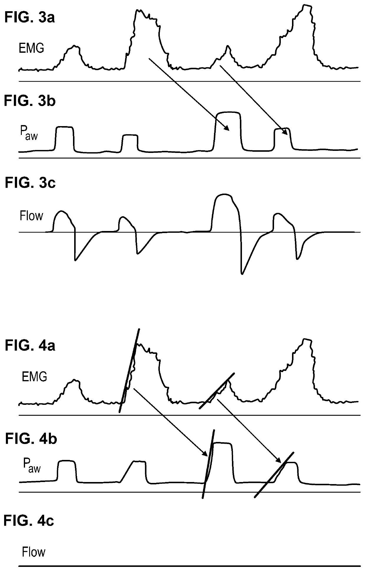
[0037]Referring to the drawings, for introduction, the general configuration of a device for the pressure-supported or pressure-controlled ventilation of a patient is shown first in FIG. 1. The device has an EMG system with electrodes 4 for recording EMG signals, which are transmitted to an EMG analysis unit 5. The EMG analysis unit 5 analyzes the received EMG signals, after which ventilator unit control signals, on the basis of which a ventilator unit 8 of the ventilator 7 is actuated as needed, are generated in the control unit 6 of the ventilator 7 on the basis of the analysis of the EMG signals recorded currently and / or at an earlier time. Furthermore, a monitor 9 is provided, on which information on the ventilation parameters set on the ventilator 7 and / or on the state of the patent, especially physiological parameters, are displayed. In particular, information relating to the breathing activity of the patient can be outputted via the monitor 9. In this connection, information ...


PUM


Abstract

A device, for the pressure-supported or pressure-controlled ventilation of a patient with reduced spontaneous breathing, has a ventilator unit to supply a breathing air flow composed of cyclical ventilation strokes and a control unit generating a control signal to set a pressure and / or a volume flow of the breathing air flow. An EMG unit generates an EMG signal, which may be used as a basis for generating the control signal as a function of a breath of the patient. A unit for analyzing an EMG signal is provided, which analyzes at least one EMG signal recorded during an already concluded breath of the patient. The control unit is configured such that the ventilator unit control signal can be generated, at least at times, by taking into account the analysis of the EMG signal recorded during an already concluded breath of the patient.

Description

CROSS REFERENCE TO RELATED APPLICATIONS[0001]This application claims the benefit of priority under 35 U.S.C. § 119 of German Application 10 2015 014 106.6 filed Nov. 3, 2015, the entire contents of which are incorporated herein by reference.FIELD OF THE INVENTION[0002]The present invention pertains to a device for the pressure-supported or pressure-controlled ventilation of a patient with reduced spontaneous breathing wherein a patient can be supplied with a breathing air flow composed of cyclical ventilation strokes, with a control device, which generates a ventilator unit control signal and transmits same to the ventilator, so that a pressure and / or a volume flow of the breathing air flow is set as a function of the ventilator unit control signal. The described device for a proportionally supporting ventilation has especially a control device, which receives signals from an EMG (electromyography) unit as a function of the patient's breathing effort, and controls the ventilator uni...

Claims


Application Information

Patent Timeline
Patent Type & Authority Patents(United States)
IPC IPC(8): A61B5/00A61M16/00A61B5/04A61B5/08A61B5/0488
CPCA61B5/08A61B5/04012A61M16/0057A61M16/026A61B5/0488A61M2205/3334A61M2016/0036A61M2016/0027A61M2230/60A61M16/00A61M2205/3331A61M2230/08A61M16/0003A61M2230/005A61B5/316A61B5/389A61B5/0826A61M16/10A61M2016/102
Inventor BAHNS, ERNSTEGER, MARCUS
Owner DRAGERWERK AG
Learn More