Device for deicing a splitter nose and inlet guide vanes of an aviation turbine engine

a technology which is applied in the field of splitter nose and guide vanes system for aviation turbine engines, can solve the problems of blockage of ice being ingested, combustion chamber flaming out, and partially or totally blocking the primary passage, so as to improve the effect of deicing

Active Publication Date: 2020-08-11
SN DETUDE & DE CONSTR DE MOTEURS DAVIATION S N E C M A
View PDF13 Cites 3 Cited by
  • Summary
  • Abstract
  • Description
  • Claims
  • Application Information

AI Technical Summary

Benefits of technology

[0006]A main object of the present invention is thus to proposed a deicer device for deicing a splitter nose and inlet guide vanes, which device provides improved deicing both of the splitter nose and also of the inlet guide vanes of the primary passage.
[0013]The angle of less than 90° between the outer surface of the hook and the axis of an injection orifice, and the orientation of said surface enable some minimum amount of clearance to exist between the hook and the outer annular wall of the splitter nose. This minimum amount of clearance serves to accelerate the stream of hot air flowing upstream into the inside of the splitter nose. Accelerating the stream of hot air inside the nose in this way increases the speed with which the hot air impacts against the end of the splitter nose, thereby improving deicing thereof. Furthermore, the shape of the hook of the invention provides a better distribution of the hot air stream in azimuth, i.e. along the splitter nose and around the longitudinal axis of the turbine engine. Conversely, in prior art devices, the flow of hot air is generally concentrated around the holes, thereby leading to nonuniform deicing of the splitter nose.
[0016]In general manner, and compared with prior art devices, for a given flow rate of hot air bled from the engine, device of the invention makes it possible to obtain better deicing of the splitter nose and better penetration of the jets of hot air into the passage. Specifically, studies have shown in particular that the jets penetrate into the passage by up to 50% more than in prior art devices based on jets of hot air.
[0018]Preferably, the outer surface of the hook forms an angle lying in the range 40° to 70° with the axis of an injection orifice. When the hook is made in this way, the angle at which each jet of hot air penetrates into the primary passage is such that the jet slopes upstream more than it would be when using an angle lying outside this range of values. This provision further increases the depth to which the jet of hot air penetrates into the passage and improves the deicing of the inlet guide vanes.
[0019]Also preferably, the hydraulic diameter D of an injection orifice satisfies the following inequality: 2%≤D / H≤6%, where H is the distance between the injection orifice and an inner wall of the primary stream flow channel. The distance H also corresponds to the height of the flow passage for the primary stream at the injection orifices. This range of values makes it possible to ensure that the jet of hot air in the passage is adapted to the dimensions of the compressor. Specifically, for values of D / H<2%, the hot air leaving the orifice flows at a rate that is too small to provide correct deicing. For values of D / H>6%, the section of an orifice is larger and the jet that is generated is characterized by a Mach number that is small, which leads to the jet being sheared rapidly by the flow of the primary stream in the passage.

Problems solved by technology

When this phenomenon occurs, it can lead to the primary passage becoming partially or totally obstructed, and to blocks of ice breaking off and being ingested in the primary passage.
In the event of blocks of ice breaking off, they can damage the compressor situated downstream and they can also lead to the combustion chamber flaming out.
Nevertheless, the holes or grooves in those devices cannot be located far enough upstream from the inlet guide vanes, which leaves little room for the jets to penetrate deeply into the primary passage so as to deice the vanes over a height that is sufficient.
Bleeding off hot air in this way can reduce the performance and the operability of the turbine engine.

Method used


Image

  • Device for deicing a splitter nose and inlet guide vanes of an aviation turbine engine
  • Device for deicing a splitter nose and inlet guide vanes of an aviation turbine engine

Examples


Embodiment Construction

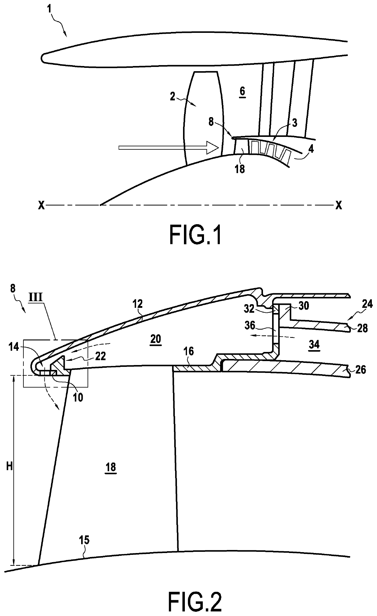
[0028]FIG. 1 shows part of an aviation turbine engine 1 of the two-spool bypass type to which the invention can be applied.

[0029]In known manner, the turbine engine 1 is axisymmetric about a longitudinal axis X-X and has an inlet at its upstream end that receives outside air, this air feeding a fan 2. Downstream from the fan 2, the air is split between a flow passage (or channel) 4 for a primary stream (or hot stream) and a flow passage 6 for a secondary stream (or cold stream). The flows in these two passages 4 and 6 are split apart from each other at the passage inlets by a splitter nose 8. Once air has entered into the primary stream flow passage 4, it then passes through a low-pressure compressor 3 (or “booster”), a high-pressure compressor, a combustion chamber, and turbines (which elements are not shown in the figures), prior to being ejected to the outside of the engine.

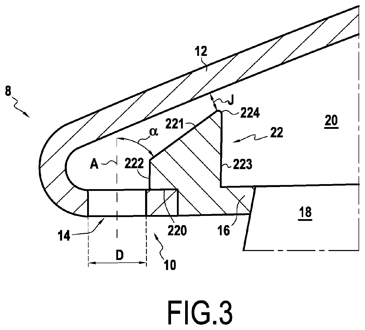
[0030]As shown in FIGS. 2 and 3, the splitter nose 8 has a longitudinal section at its upstream edge that i...


PUM


Abstract

A deicer device deices both a splitter nose and inlet guide vanes of an aviation turbine engine. The device includes a splitter nose to split a stream coming from the fan into primary and secondary stream flow channels of annular shape and an inner shroud to which inlet guide vanes are fastened and including a hook that holds the inner shroud axially at its upstream end against the inner annular wall. An outer surface facing of the hook forms an angle of less than 90° with an injection orifice such that the outer surface comes progressively closer to the outer annular wall on going away from the injection orifice. The outer surface of the hook presents a minimum amount of clearance J relative to the outer annular wall such that 0.2≤J / D≤0.6 where D is the hydraulic diameter of an injection orifice.

Description

BACKGROUND OF THE INVENTION[0001]The present invention relates to the general field of turbine engines. The invention relates more particularly to a system for deicing a splitter nose and inlet guide vanes of the primary passage through the turbine engine.[0002]In an aviation turbine engine of the two-spool bypass type, the primary and secondary streams are split into respective flow passages downstream from the fan by means of a splitter nose. Within the primary passage, at the inlet to the low-pressure compressor (also commonly referred to as a “booster”), there is to be found a set of inlet guide vanes (IGVs).[0003]During certain stages of flight, and also on the ground, the engines may encounter icing atmospheric conditions, in particular when ambient temperature is low enough and when humidity is high. Under such conditions, ice can form on the splitter nose and on the inlet guide vanes. When this phenomenon occurs, it can lead to the primary passage becoming partially or total...

Claims


Application Information

Patent Timeline
Patent Type & Authority Patents(United States)
IPC IPC(8): F02C7/047F01D25/02F01D25/24F02K3/06B64D15/04
CPCB64D15/04F02C7/047F01D25/02F02K3/06F01D25/246F05D2240/121B64D2033/0233
Inventor SCHOLTES, CHRISTOPHEBRUNET, ANTOINE ROBERT ALAINAMOEDO, SIMON JOSE PIERRE
Owner SN DETUDE & DE CONSTR DE MOTEURS DAVIATION S N E C M A
Why Eureka
Try Eureka