Measurement method using an inductive displacement sensor

a technology of inductive displacement and measurement method, which is applied in the direction of measuring device, sensor output conversion, instruments, etc., can solve the problems of reducing response time and increasing the refreshing of measurement, and achieve the effect of simplifying the acquisition chain, improving the response time and the precision of inductive displacement sensors

Active Publication Date: 2020-08-11
SAFRAN ELECTRONICS & DEFENSE
View PDF9 Cites 0 Cited by
  • Summary
  • Abstract
  • Description
  • Claims
  • Application Information

AI Technical Summary

Benefits of technology

[0012]The object of the invention is to improve the response time and the precision of an inductive displacement sensor and of an acquisition chain connected to said inductive displacement sensor, and to simplify said acquisition chain.SUMMARY OF THE INVENTION
[0023]The measurement is therefore insusceptible to environmental noise. Moreover, an estimate of the position of the magnetic core can be produced after each acquisition of a new sampled value of each measurement voltage, which reduces the response time and increases refreshing of the measurement.
[0024]Finally, the measurement method according to the invention can be performed using a single analog-to-digital converter which acquires the two measurement voltages alternately (the sampling rate of the analog-to-digital converter is doubled but just one analog-to-digital converter is used rather than two). The acquisition chain connected to the inductive displacement sensor is thus simplified, and the gain error that exists in the case of two separate analog-to-digital converters is eliminated.

Problems solved by technology

Moreover, an estimate of the position of the magnetic core can be produced after each acquisition of a new sampled value of each measurement voltage, which reduces the response time and increases refreshing of the measurement.

Method used


Image

  • Measurement method using an inductive displacement sensor
  • Measurement method using an inductive displacement sensor
  • Measurement method using an inductive displacement sensor

Examples


Embodiment Construction

[0035]The invention is implemented in the present case in a system comprising an LVDT sensor and a computer connected to the LVDT sensor.

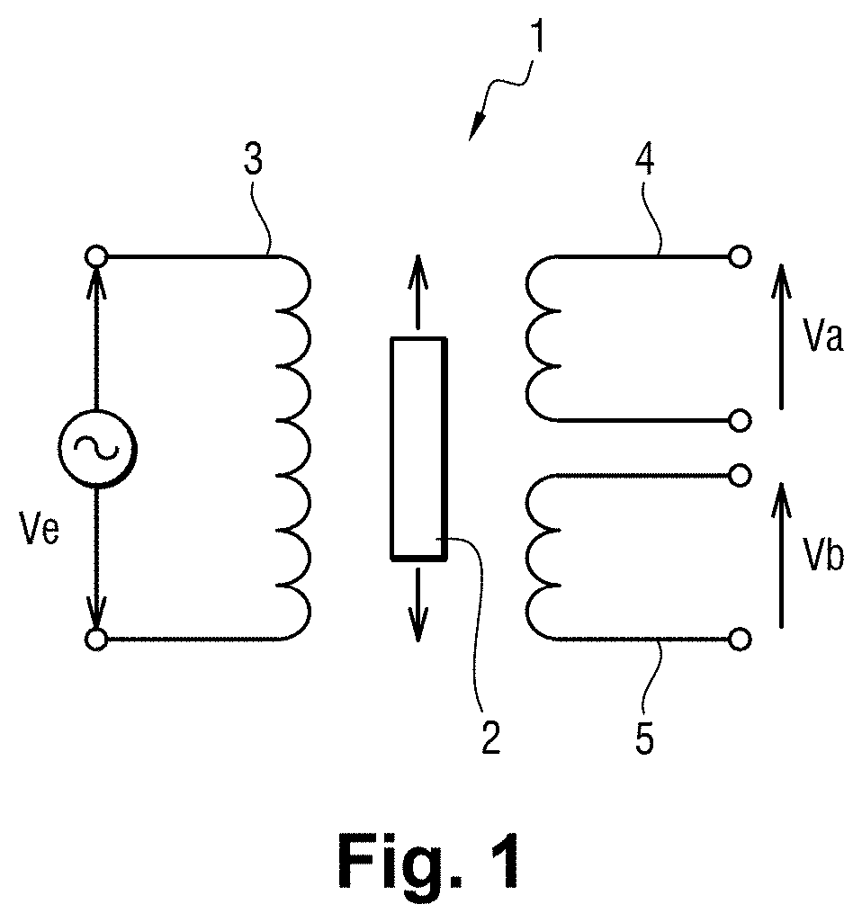
[0036]The LVDT sensor is similar to the LVDT sensor 1 that has just been described.

[0037]The computer includes a processing component and an acquisition chain that comprises an analog-to-digital converter. The processing component and the analog-to-digital converter are designed to perform the measurement method according to the invention.

[0038]The processing component in the present case is an FPGA, but it could perfectly well be a different component, for example a processor, a microcontroller or an ASIC.

[0039]The measurement method firstly allows a position of the magnetic core 2 of the LVDT sensor 1 to be estimated.

[0040]For this purpose, the measurement method firstly includes an excitation phase.

[0041]During the excitation phase, the computer produces an excitation voltage Ve which is applied across the terminals of the primary winding 3 of t...


PUM


Abstract

A measurement method using an inductive displacement sensor including a magnetic core and transformer with a primary winding and two secondary windings. The method includes an excitation phase of applying an AC excitation voltage across the primary winding terminals; acquisition phase for acquiring and digitizing two measurement voltages across the two secondary windings' terminals; first main processing phase performed on two measurement voltages including the steps of: multiplying the measurement voltage by a reference sine wave and reference cosine wave to obtain two resulting signals; carrying out a first integration of each resulting signal over a sliding window with width equal to the excitation period to obtain two integrated signals; carrying out a second integration of each integrated signal over a sliding window with width equal to half an excitation period to obtain two doubly integrated signals; producing amplitude of the measurement voltage from the doubly integrated signals; first final processing phase for producing a positional estimate of the magnetic core from the amplitudes of the two measurement voltages.

Description

[0001]The invention relates to the field of measurement methods using an inductive displacement sensor.BACKGROUND OF THE INVENTION[0002]With reference to FIG. 1, an LVDT (for Linear Variable Differential Transformer) sensor 1 conventionally includes a cylindrical body in which a transformer and a magnetic core 2 are integrated.[0003]The transformer comprises a primary winding 3, a first secondary winding 4 and a second secondary winding 5. The magnetic core 2 slides axially within the cylindrical body and thus changes the distribution of the magnetic field that prevails in said cylindrical body.[0004]An excitation voltage Ve is applied across the terminals of the primary winding 3. The excitation voltage Ve has a specific excitation period and a specific excitation frequency. A first measurement voltage Va is measured across the terminals of the first secondary winding 4 and a second measurement voltage Vb is measured across the terminals of the second secondary winding 5.[0005]The ...

Claims


Application Information

Patent Timeline
Patent Type & Authority Patents(United States)
IPC IPC(8): G01D5/22G01D18/00G01D5/20
CPCG01D5/2291G01D18/00G01D5/2053
Inventor BOCAGE, FRÉDÉRICSAUVENT, DANIEL
Owner SAFRAN ELECTRONICS & DEFENSE
Why Eureka
Try Eureka