System and method for reactive power control of a wind turbine by varying switching frequency of rotor side converter

a technology of reactive power control and rotor side converter, which is applied in the direction of passive/reactive control, electric generator control, machines/engines, etc., can solve the problems of reduced total output current capability of rsc, peak temperatures and thermal cycling stresses, and reduced reactive power capability of rs

Active Publication Date: 2020-08-11
GENERAL ELECTRIC CO
View PDF72 Cites 7 Cited by
  • Summary
  • Abstract
  • Description
  • Claims
  • Application Information

AI Technical Summary

Benefits of technology

[0012]The second switching frequency may also be based on maintaining total harmonic distortion (THD) of the system within defined limits, whi

Problems solved by technology

This results in a reduction of the total output current capability of the RSC, and thus a reduction in the reactive power capability of the RSC.
While this elevated switching frequency is desirable for most operating speeds, at or near synchronous generator rotor speeds, it generates peak temperatures and thermal cycling st

Method used


Image

  • System and method for reactive power control of a wind turbine by varying switching frequency of rotor side converter
  • System and method for reactive power control of a wind turbine by varying switching frequency of rotor side converter
  • System and method for reactive power control of a wind turbine by varying switching frequency of rotor side converter

Examples


Embodiment Construction

[0033]Reference now will be made in detail to embodiments of the invention, one or more examples of which are illustrated in the drawings. Each example is provided by way of explanation of the invention, not limitation of the invention. In fact, it will be apparent to those skilled in the art that various modifications and variations can be made in the present invention without departing from the scope or spirit of the invention. For instance, features illustrated or described as part of one embodiment can be used with another embodiment to yield a still further embodiment. Thus, it is intended that the present invention covers such modifications and variations as come within the scope of the appended claims and their equivalents.

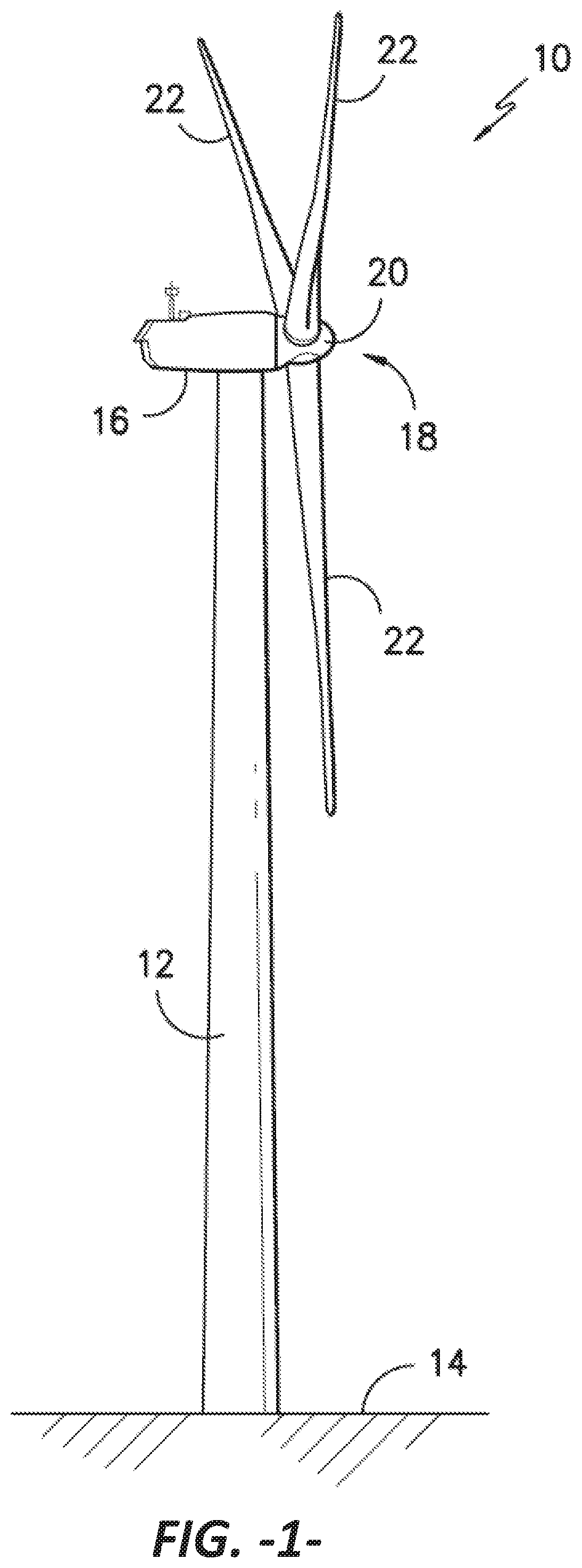
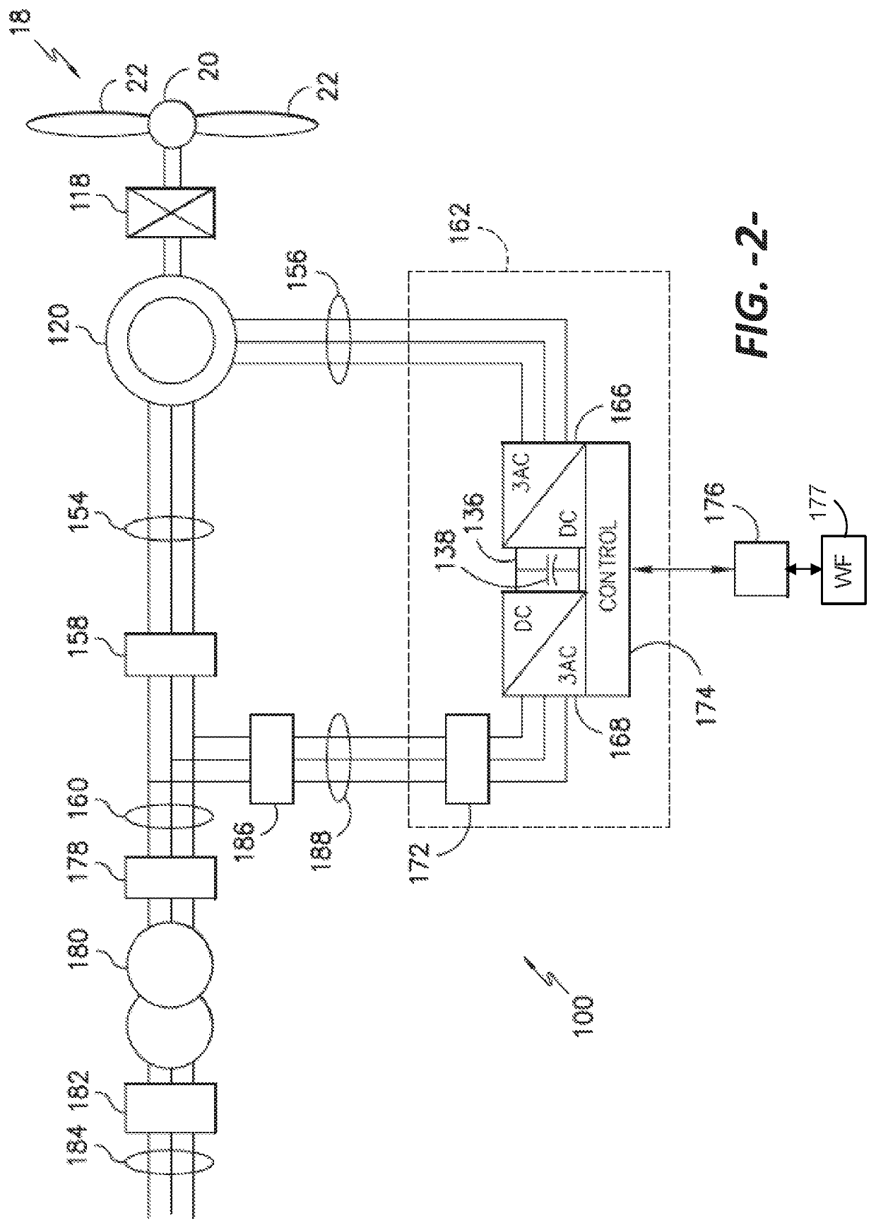
[0034]In general, the present subject matter is directed to a system and method for operating a power generation system, such as a wind turbine configured with a doubly fed induction generator (DFIG) system. As mentioned, in a particular embodiment of the s...


PUM


Abstract

A method and associated system for operating a power generation system to provide real and reactive power to a load includes, with a power converter having switching elements, receiving power from a generator and generating the reactive power within an operating range of generator rotor speed. As the generator rotor speed changes and approaches synchronous speed, a control command is generated to decrease a switching frequency of the switching elements in the power converter from a first switching frequency to a second switching frequency, wherein the reactive power output of the power converter is maintained or increased at the second switching frequency.

Description

FIELD[0001]The present disclosure relates generally to wind turbines and, more particularly, to a system and method to enhance reactive power capability of the wind turbine by controlling the switching frequency of the rotor-side converter (RSC) in a doubly-fed induction generator (DFIG) system.BACKGROUND[0002]Generally, during operation of a wind turbine, wind impacts the rotor blades and the blades transform wind energy into a mechanical rotational torque that drives a low-speed shaft. The low-speed shaft drives a gearbox that subsequently steps up the low rotational speed of the low-speed shaft to drive a high-speed shaft at an increased rotational speed, wherein the high-speed shaft rotatably drives a generator rotor. In many conventional wind turbine configurations, the generator is electrically coupled to a bi-directional power converter that includes a rotor-side converter (RSC) joined to a line-side converter (LSC) via a regulated DC link. Each of the RSC and the LSC typical...

Claims


Application Information

Patent Timeline
IPC IPC(8): H02M5/458H02P9/30F03D9/25H02J3/18H02P9/00H02M1/42H02P9/42H02J3/38H02P9/10H02P101/15
CPCH02P9/30F03D9/255H02M5/4585H02M1/42H02P9/007H02P9/42H02J3/1842H02P9/105H02J3/386F05B2270/327F05B2270/402F05B2220/706H02P2101/15F03D7/042F03D7/0272F03D7/028F03D7/0284H02J3/16H02J3/381H02J2300/28H02M1/12Y02E40/30
Inventor GADIRAJU, KASI VISWANADHA RAJURAY, OLIVEJHA, KAPILKOLHATKAR, YASHOMANI YASHODHAN
Owner GENERAL ELECTRIC CO
Why Eureka
Try Eureka