Microphone and Method to Position a Membrane Between Two Backplates

a backplate and microphone technology, applied in the field of microphones, can solve the problems of insufficient precision that can be achieved during manufacturing, and achieve the effect of optimizing the maximum sound pressure level (max spl) and minimizing the total harmonic distortion (thd)

Active Publication Date: 2014-02-06
TDK CORPARATION
View PDF12 Cites 14 Cited by
  • Summary
  • Abstract
  • Description
  • Claims
  • Application Information

AI Technical Summary

Benefits of technology

[0030]This method can be repeated several times until the membrane is precisely centered at its final electro-mechanic equilibrium position between the two backplates. This feedback system also allows the bias voltages to be adjusted based on the measured capacitance.
[0031]By adjusting the position of the membrane between the two backplates the microphone becomes acoustically symmetric. This optimizes the maximum sound pressure level (MAX SPL) and minimizes the total harmonic distortion (THD). The MAX SPL describes how much acoustic pressure can be applied to the microphone until the membrane is pulled towards one of the backplates. Preferably, the MAX SPL should be as high as possible as MAX SPL describes the measurement range of the microphone. The THD describes how much the signal is distorted at a given sound pressure level. The THD is minimized by the present invention.

Problems solved by technology

However, the precision that can be achieved during manufacturing is not accurate enough to fulfill the increasing demands concerning the specifications of microphones.

Method used


Image

  • Microphone and Method to Position a Membrane Between Two Backplates
  • Microphone and Method to Position a Membrane Between Two Backplates

Examples


Embodiment Construction

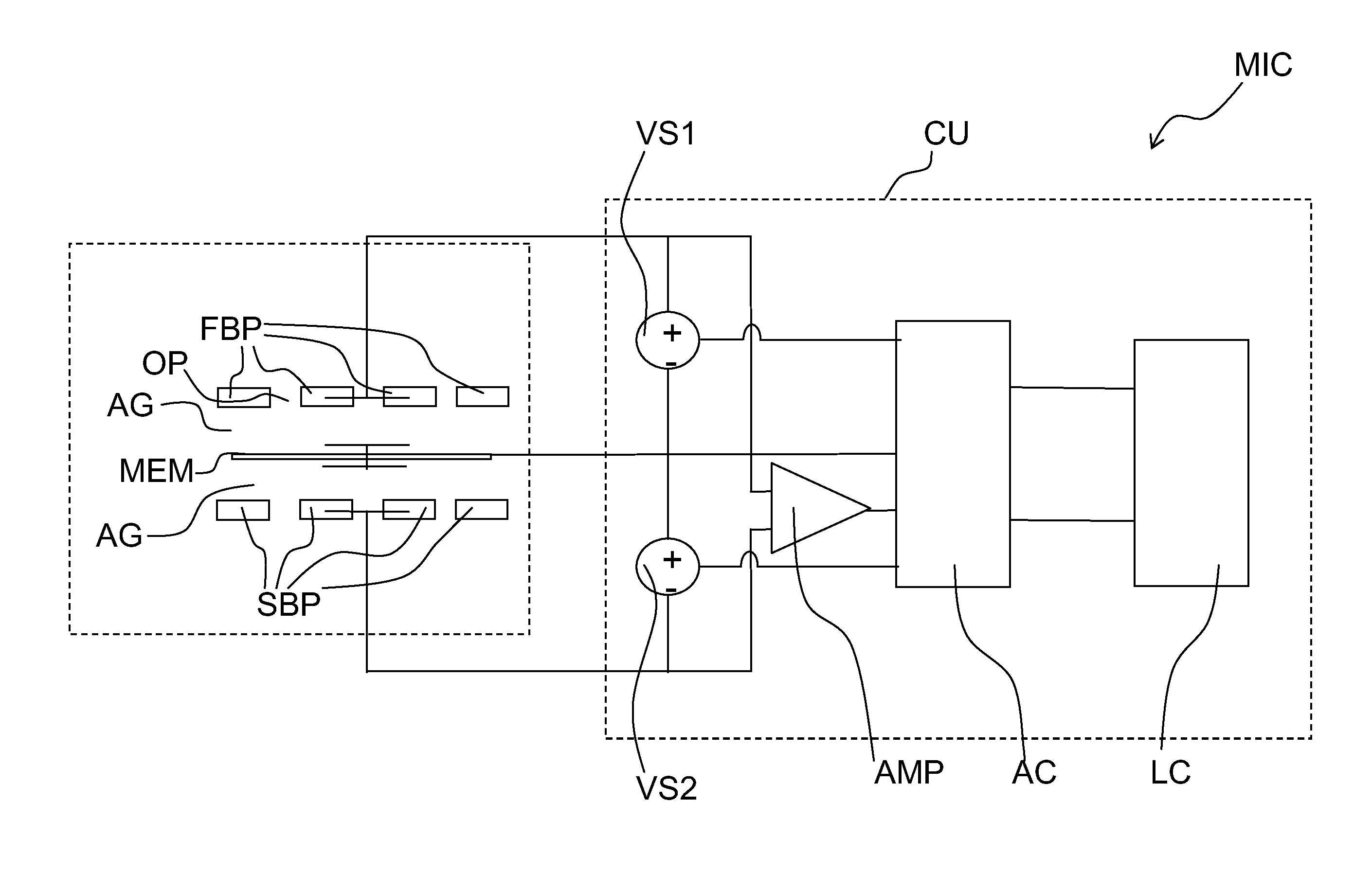
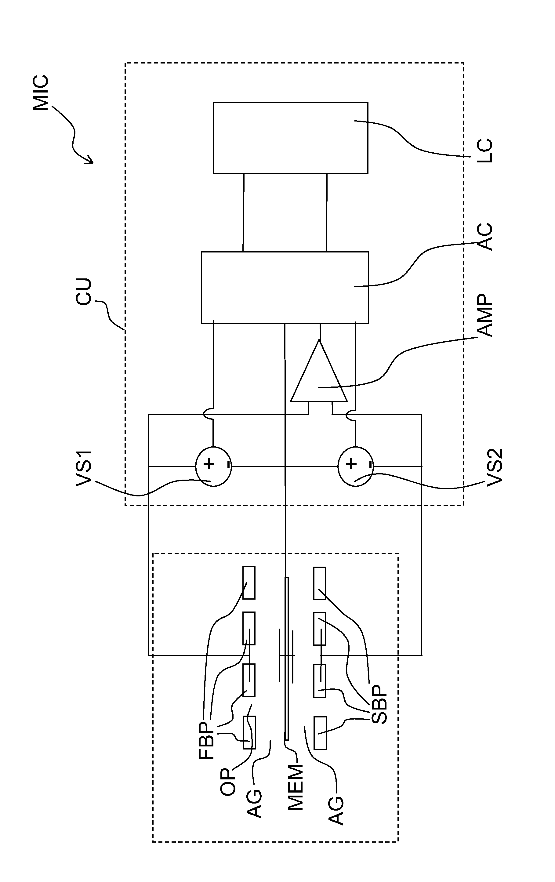
[0034]The FIGURE shows a dual backplate MEMS microphone MIC according to the present invention. The microphone MIC comprises a first backplate FBP and a second backplate SBP. Further, the microphone MIC comprises a membrane MEM that is located between the first and the second backplate FBP, SBP. There is an air-gap AG between the membrane MEM and each of the backplates FBP, SBP. The first and the second backplate FBP, SBP each comprise openings OP so that the air-gaps AG and the membrane MEM are in contact with the environment. If an acoustic signal applies a pressure to the microphone MIC, the acoustic signal can propagate through the openings OP of the backplates FBP, SBP and the membrane MEM is moved by the corresponding pressure variation.

[0035]Further, the microphone MIC comprises a control unit CU which comprises two voltage sources VS1, VS2. The control unit CU can be integrated on a single chip together with the membrane MEM and the backplates FBP, SBP, located on a dedicate...


PUM


Abstract

A microphone includes two backplates. A membrane is located between the two backplates. A voltage source applies a first bias voltage to the membrane and the first backplate and applies a second bias voltage to the membrane and the second backplate. A control unit adjusts the first and the second bias voltage. A method to center the membrane in a final electro-mechanic equilibrium position between the two backplates in a microphone is also disclosed.

Description

[0001]This patent application is a national phase filing under section 371 of PCT / EP2011 / 053329, filed Mar. 4, 2011, which is incorporated herein by reference in its entirety.TECHNICAL FIELD[0002]The present invention concerns a microphone. In particular embodiments, the present invention concerns a dual backplate microphone comprising two backplates and a membrane located between the two backplates. In further embodiments, the present invention provides a method to position a membrane between two backplates of a dual backplate microphone.BACKGROUND[0003]Compared to a regular microphone comprising a membrane and one backplate, a dual backplate microphone provides a performance increase on the same chip area. In a dual backplate microphone, a first capacitance between the membrane and the first backplate is measured and simultaneously a second capacitance between the membrane and the second backplate is measured. Compared to a single backplate microphone, the performance is increased...

Claims


Application Information

Patent Timeline
Patent Type & Authority Applications(United States)
IPC IPC(8): H04R19/04
CPCH04R19/04
Inventor MORTENSEN, DENNIS
Owner TDK CORPARATION
Why Eureka
Try Eureka