Miniature imaging system for ophthalmic laser beam delivery system

a laser beam and optical imaging technology, applied in the field of optical imaging systems, can solve the problems of limiting the freedom of manipulating the patient interface device during docking, blocking the surgeon's view of the eye,

Active Publication Date: 2020-08-18
AMO DEVMENT
View PDF17 Cites 0 Cited by
  • Summary
  • Abstract
  • Description
  • Claims
  • Application Information

AI Technical Summary

Benefits of technology

[0007]An object of the present invention is to provide an imaging system for an ophthalmic laser beam delivery system while minimizing the space occupied by the imaging system near the lower end of the beam delivery head.

Problems solved by technology

One disadvantage of the configuration shown in FIG. 1 is that the imaging module housing 29 is bulky, and due to its location right above the lowest point 29a of the delivery head, blocks the surgeon's view of the eye and limits the freedom to manipulate the patient interface device during docking.

Method used


Image

  • Miniature imaging system for ophthalmic laser beam delivery system
  • Miniature imaging system for ophthalmic laser beam delivery system
  • Miniature imaging system for ophthalmic laser beam delivery system

Examples


Embodiment Construction

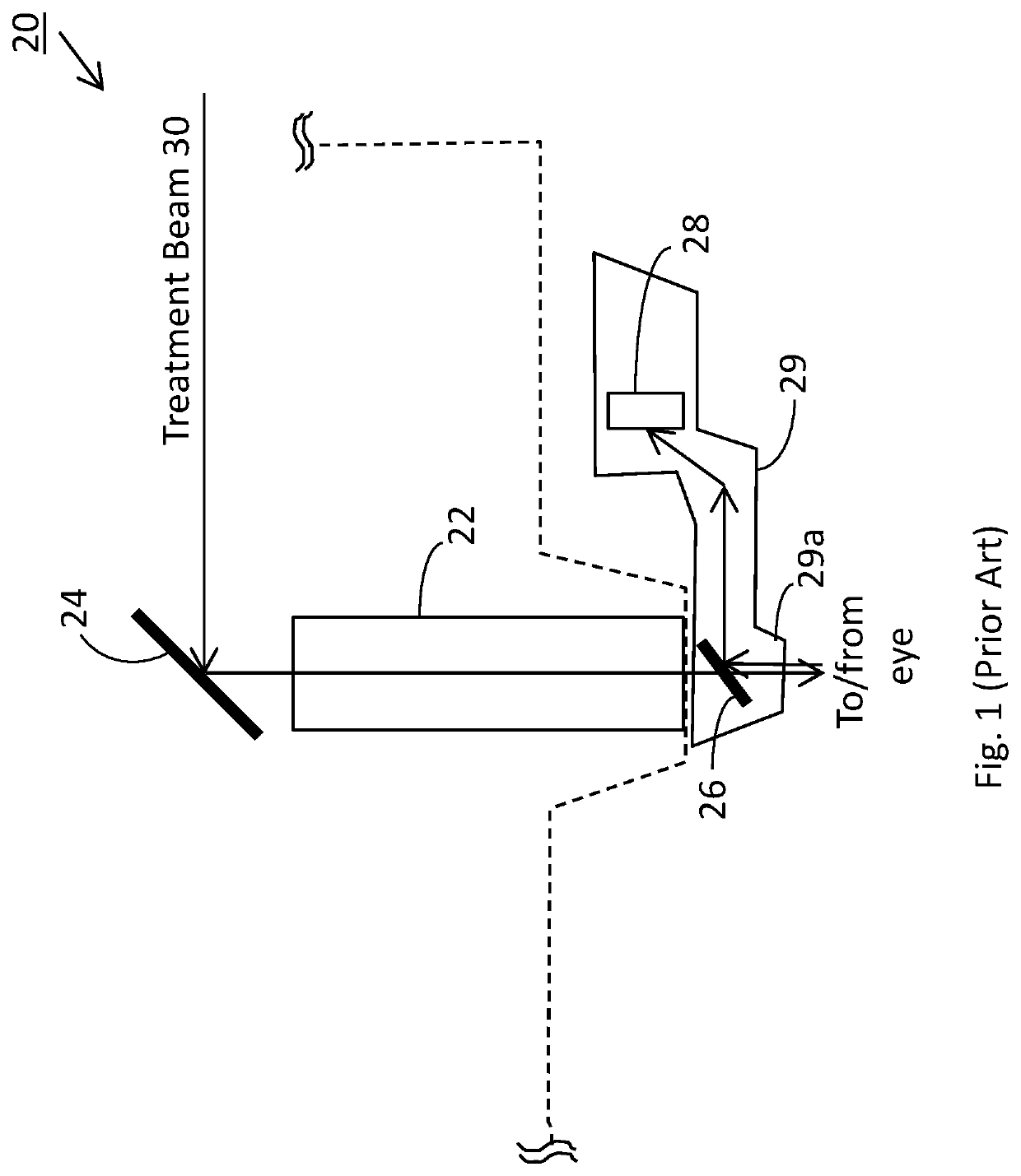
[0015]According to an embodiment of the present invention, the conventional beam delivery system shown in FIG. 1 is modified by providing an imaging sensor and related optics on the back side of the folding mirror 24 / 14, i.e. the mirror that reflects the treatment beam 30 to the entrance of the focusing objective 22. Thus, some structures shown in FIG. 1, including the beam splitter 26 located at the exit of the focusing objective 22 and the imaging sensor 28 located in the imaging module housing 29, can be eliminated; as a result, the housing 29 can be significantly reduced in size, or eliminated, so that on both sides of the focusing objective there is sufficient free space to accommodate the patient's nose bridge. Therefore, a rotatable housing is not necessary, and the surgeon will have much improved visibility of the patient's eye and room to manipulate the patient interface during docking.

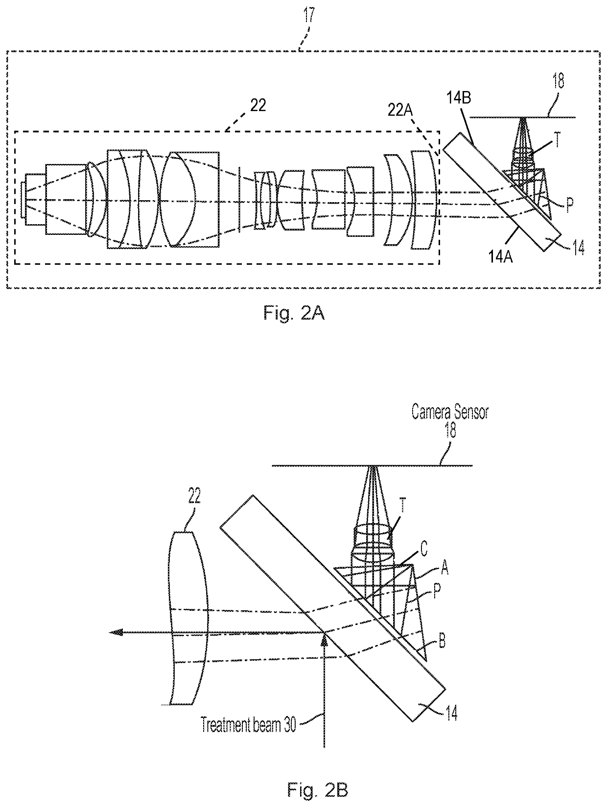
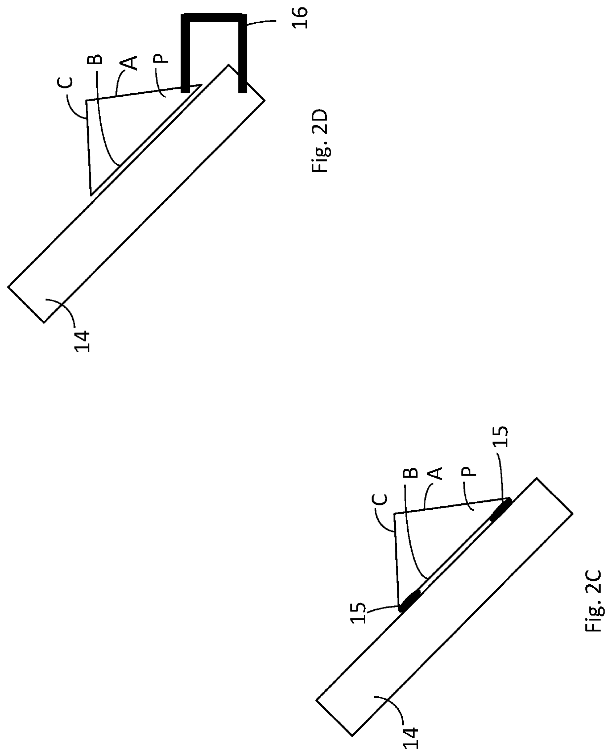
[0016]FIGS. 2A and 2B schematically illustrates the structure of the imaging system accor...


PUM


Abstract

An optical imaging system for an ophthalmic laser beam delivery system, which includes a focusing objective including a plurality of lenses, a semi-transparent folding mirror disposed near an entrance of the focusing objective for reflecting a treatment laser beam into the focusing objective, a prism disposed adjacent a back surface of the folding mirror, the prism having a first, a second and a third surface, the second surface being disposed adjacent the back surface of the folding mirror, the prism being configured to reflect a light that has entered the second surface sequentially by the first surface and by the second surface toward the third surface to be output, a focusing lens module disposed adjacent the third surface of the prism to focus light output from the third surface of the prism, and an image sensor disposed to receive the light focused by the focusing lens module to form an image.

Description

BACKGROUND OF THE INVENTIONField of the Invention[0001]This invention relates to an optical imaging system, and in particular, it relates to a miniature optical imaging system for an ophthalmic laser beam delivery system.Description of Related Art[0002]In a laser system for ophthalmic surgery, the laser beam from a laser device (the treatment laser beam) is delivered by a laser beam delivery optical system to the patient's eye to treat the eye. A part of the beam delivery system is located in a delivery head of the laser system, which is moveably mounted on a mounting structure and is brought to the proximity of the eye for performing the treatment. Typically, an optical imaging system is provided for the beam delivery system to capture light from the eye. The light from the eye may be, for example, light backscattered, reflected, or refracted from the eye, or otherwise generated by the eye under illumination by an illumination light or in response to the treatment laser beam, such ...

Claims


Application Information

Patent Timeline
Patent Type & Authority Patents(United States)
IPC IPC(8): A61B3/14G02B17/08G02B5/04G02B23/02G02B17/04G02B27/10G02B27/14A61F9/008A61B18/22
CPCG02B27/14G02B17/08G02B17/045G02B5/04G02B27/108A61B3/14G02B23/02A61B2018/2261A61F9/008A61F2009/00897
Inventor SUN, ZHENG
Owner AMO DEVMENT
Why Eureka
Try Eureka