Fastening method

a fastening element and fastening technology, applied in the direction of fastening means, nuts, sheet joining, etc., can solve the problem of limited effective length of the fastening element for anchoring in the blind bor

Active Publication Date: 2020-08-18
HILTI AG
View PDF24 Cites 2 Cited by
  • Summary
  • Abstract
  • Description
  • Claims
  • Application Information

AI Technical Summary

Benefits of technology

[0019]According to an embodiment the mean diameter is less than or equal to 8 mm, preferably less than or equal to 7 mm, particularly preferably less than or equal to 6 mm. As a result in some circumstances the blind bore can be produced in a relatively short time with a hand-held drilling machine.

Problems solved by technology

In plate-shaped base elements with a predetermined thickness, which furthermore should not be drilled through, the depth of the blind bore and thus the effective length of the fastening element for anchoring in the blind bore is limited.

Method used


Image

  • Fastening method

Examples


Embodiment Construction

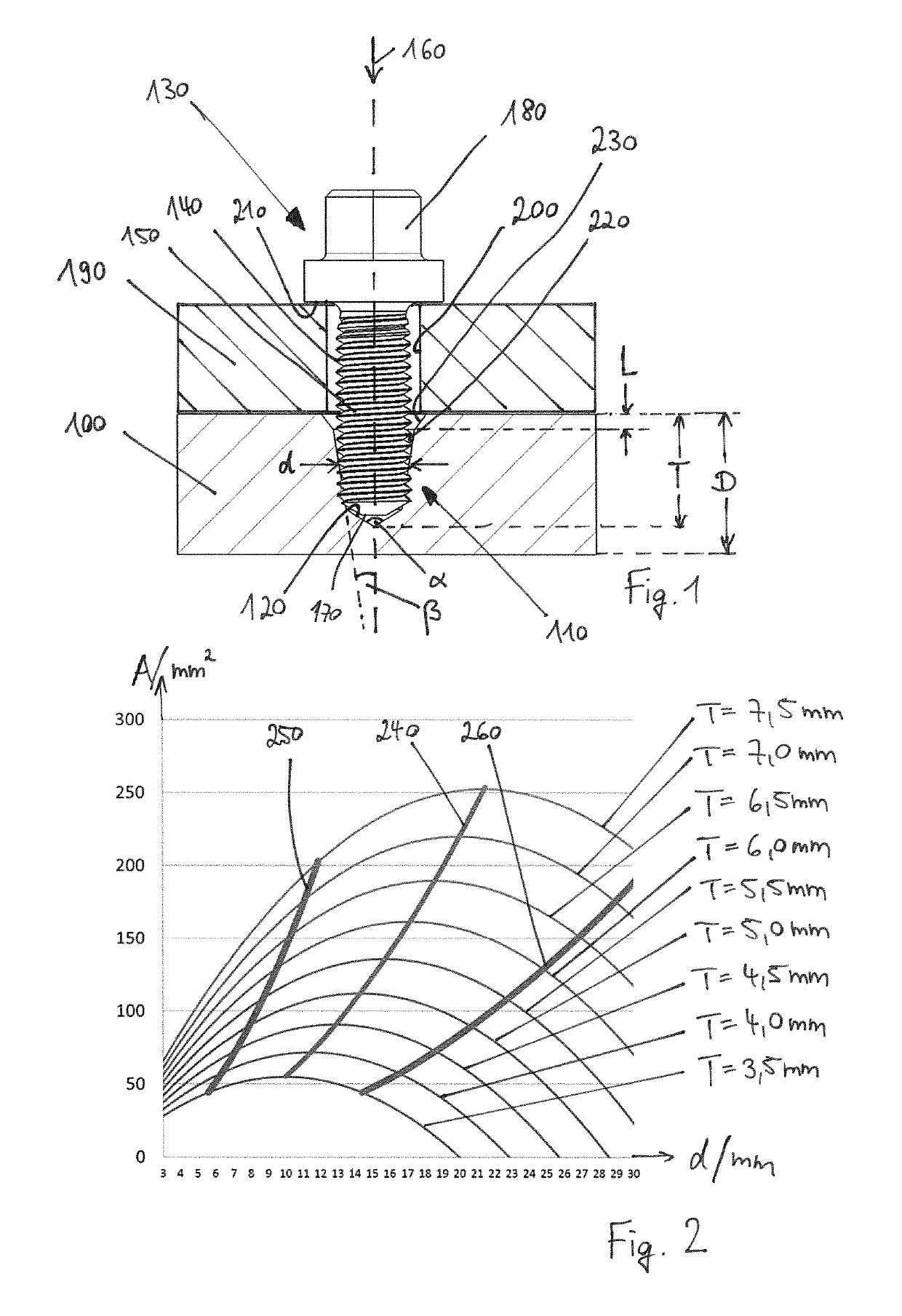
[0024]In FIG. 1 a plate 100 is shown which, within the context of the invention, constitutes a base element. The plate 100 preferably comprises or consists of metal, in particular aluminum, or an alloy, in particular steel, or concrete, in particular cellular concrete, or plastic or wood, and preferably forms a wall or a floor for example of a ship, a drilling rig or an industrial building. For fastening of a component 190 to the panel 100, a through hole 200 is drilled into the component 190 and a blind bore 110, which defines a depth direction 160 and at a depth T has a blind bore base 120, is drilled into the plate 100. The through hole 200 and the blind bore 110 are preferably drilled one after the other. In the exemplary embodiments which are not illustrated, the through hole and the blind bore are produced in one single drilling operation, for example by drilling through the component into the base element.

[0025]The blind bore base 120 is conical with a cone opening angle α. A...


PUM


Abstract

A method for fastening a component to a base element, in which method there is produced in the base element a blind bore which defines a depth direction and which has a force transmission surface which has a depth T in the depth direction, wherein the force transmission surface is of frustoconical form with a cone opening half-angle (β) and a mean diameter (d), wherein the blind bore has a conical blind bore base with a cone opening angle (α) and, at the edge thereof, a bevel which extends in the depth direction to a bevel depth L, wherein, in the method, a fastening element is anchored in the blind bore by way of the force transmission surface, and wherein the component is held by the fastening element.

Description

CROSS-REFERENCE TO RELATED APPLICATIONS[0001]This patent application is the U.S. National Stage of International Patent Application No. PCT / EP2015 / 056978, filed Mar. 31, 2015, which claims the benefit of European Patent Application No. 14163294.3, filed Apr. 3, 2014, which are each incorporated by reference.BACKGROUND OF THE INVENTION[0002]The present invention relates to a method for fastening a component to a base element, wherein a blind bore is produced in the base element, a fastening element is anchored in the blind bore, and the component is held by the fastening element.[0003]Blind bores are usually produced by drills which are equipped with cutting edges at their tips. The cutting edges are arranged inclined relative to a depth direction of the respective blind bore and produce a conical blind bore base by rotation about the depth direction. An edge of the blind bore generally has a bevel, so that between the bevel and the blind bore base a force transmission surface is for...

Claims


Application Information

Patent Timeline
Patent Type & Authority Patents(United States)
IPC IPC(8): F16B5/02F16B37/00B23B51/00
CPCB23B51/0081F16B37/005F16B5/02
Inventor FOSER, THOMAS
Owner HILTI AG
Why Eureka
Try Eureka