Method and device for bonding of substrates

a technology of substrate bonding and substrate, which is applied in the direction of microstructural devices, coatings, microstructured technology, etc., can solve the problems of no longer being able to increase the lateral density of functional units, the alignment accuracy of functional units cannot be increased at all, and the physical and technological limitations cannot be overcome. achieve the effect of increasing the bonding quality, in particular the bonding accuracy, especially at the edge of the substra

Active Publication Date: 2020-08-25
EV GRP E THALLNER GMBH
View PDF52 Cites 1 Cited by
  • Summary
  • Abstract
  • Description
  • Claims
  • Application Information

AI Technical Summary

Benefits of technology

[0036]The present invention overcomes problems of the prior art to provide a device and a method for bonding two substrates, with which the bonding quality, in particular the bonding accuracy, especially at the edge of the substrates, is increased.

Problems solved by technology

In some sub-sectors of microelectronics or microsystem technology, even to an extent such that a further increase in the lateral density of the functional units is no longer possible.
In a few years, therefore, physical and technological limitations will no longer permit any increase at all in the lateral density of functional units.
One of the greatest technical problems with the permanent bonding of two substrates is the alignment accuracy of the functional units between the individual substrates.
Although the substrates can be precisely aligned with respect to one another by means of alignment equipment, distortions of the substrates can arise during the bonding process itself.
As a result of the distortions thus arising, the functional units will not necessarily be correctly aligned with one another at all positions.
The alignment inaccuracy at a specific point on the substrate may be a result of a distortion, a scaling error, a lens error (magnification or reduction error) etc.
During the production of the functional units, it can however be seen that there is always a deviation between the ideal functional units designed on the computer and the real functional units produced in the clean room.
The differences are primarily due to natural variations in the materials used, such as for example different number of the different isotopes in the substrate material, limitations of the hardware, i.e. engineering-related problems, but very often physical limitations.
Thus, the resolution accuracy of a structure that is produced by a photolithographic process is limited by the size of the apertures of the photomask and the wavelength of the light used.
It is not therefore surprising that the functional units of a substrate cannot be identical to the structures designed on the computer.
If the positions and / or shapes of two opposite-lying functional units of two substrates are compared on the assumption that neither of the two substrates is distorted by a bonding process, it is found that in general there is already an imperfect congruence of the functional units, since the latter diverge from the ideal computer model due to the errors described above.
A local overlay error arises in a location-dependent manner, mainly due to elasticity and / or plasticity problems, in the present case primarily caused by the continuously propagating bonding wave.
This error arises primarily due to a distortion of at least one substrate during a bonding process.
Errors I. and II. can however also arise due to a bonding process, but they are usually superimposed by errors III. and IV. to such a marked extent that it is difficult to detect or measure th

Method used


Image

  • Method and device for bonding of substrates
  • Method and device for bonding of substrates
  • Method and device for bonding of substrates

Examples


first embodiment

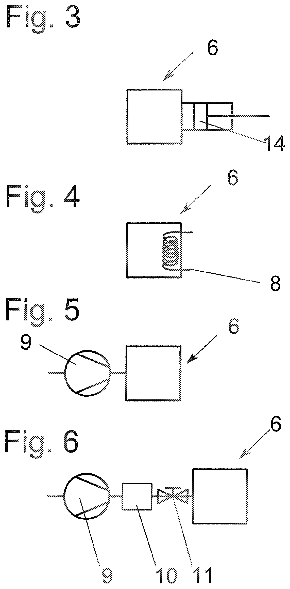
[0164]FIG. 3 represents a schematic block diagram of a bonding chamber 6, wherein the in particular dynamic and constant increase in the chamber pressure takes place by means of a change in the bonding chamber volume, in particular by means of piston 14, so that the number of particles in bonding chamber 6 during the bonding process remains constant with changing pressure in an observation period, in particular between the end positions (not shown) of the piston. When there is a change in the volume of the sealed bonding chamber, no gas particles accordingly enter into the sealed system of the bonding chamber volume; likewise, no particles are removed. The particle number thus remains constant and the gas laws for ideal gases can thus be applied. In the embodiment, a targeted supply of the generated excess pressure in the case of a compression is to be conveyed via, for example, a nozzle system, described in FIG. 2, to the appropriate point.

second embodiment

[0165]FIG. 4 is a schematic block diagram of a bonding chamber 6. The inventive increase in the pressure takes place via the change, in particular the increase, in the temperature by suitable heating means 8. The number of particles in bonding chamber 6 during the bonding process can remain constant with a sealed system. With a temperature change of the sealed bonding chamber, no gas particles accordingly enter into the sealed system of the bonding chamber volume; likewise, no particles are removed. The particle number thus remains constant and the gas laws for ideal gases can thus be applied. In the embodiment, a targeted supply of the generated excess pressure (generated by a thermal energy supply) is to be conveyed via, for example, a nozzle system, described in FIG. 2, to the appropriate point.

third embodiment

[0166]FIG. 5 is a schematic block diagram of a bonding chamber 6 according to the invention, wherein the in particular dynamic and constant increase in the chamber pressure can take place by suitable compressor units 9, pumps. Particle-free air, nitrogen, argon, helium, carbon dioxide or other inert gases can be pumped at high pressure into the bonding chamber. As discussed in FIG. 2, and not shown here, a targeted supply of the generated excess pressure can influence the bonding wave, according to the invention, via a suitable nozzle system.

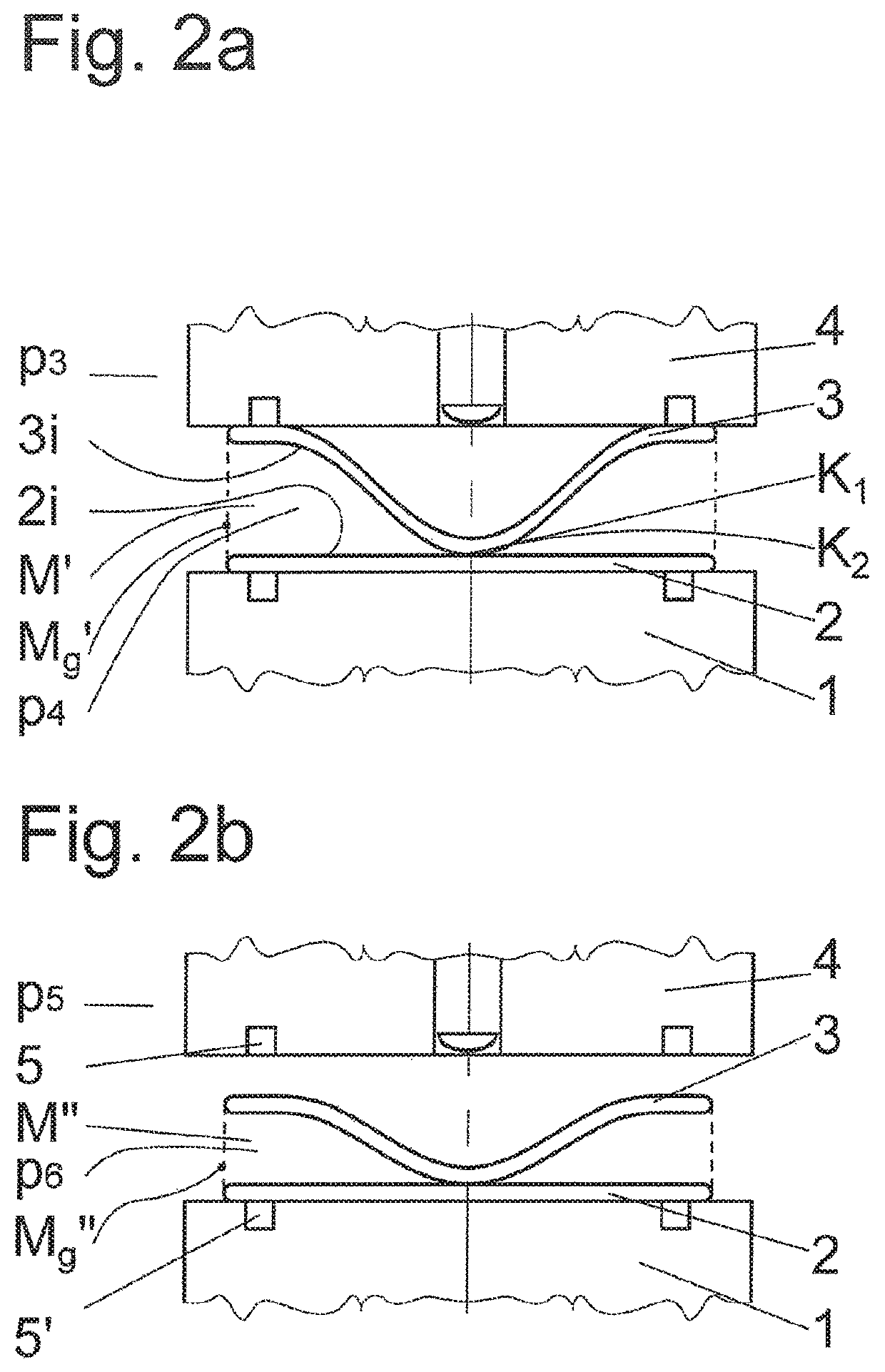
[0167]FIG. 6 represents an extension of the third embodiment of a bonding chamber 6 represented in FIG. 5. Here, an excess pressure is generated by means of a compressor unit 9, which fills a storage unit 10, in particular a pressure vessel. By means of suitable valves 11, the excess pressure can also be conveyed, as disclosed in FIG. 2a, 2b, to the appropriate points of spatial section interface Mg′ or Mg″ and the bonding wave can be influenced...


PUM

PropertyMeasurementUnit
speedaaaaaaaaaa
speedaaaaaaaaaa
speedaaaaaaaaaa

Abstract

A method and a device for bonding a first substrate with a second substrate inside a sealed bonding chamber. The method includes: a) fixing of the first and second substrates, b) arranging of the first and second substrates, c) mutual approaching of the first and second substrates, d) contacting the first and second substrates at respective bond initiation points, e) generating a bonding wave running from the bond initiation points to side edges of the substrates, and f) influencing the bonding wave during course of the bonding wave, wherein targeted influencing of the bonding wave takes place by a regulated and / or controlled change of pressure inside the bonding chamber.

Description

Field of the invention[0001]The invention relates to a method and a device for bonding a first substrate with a second substrate.Background of the Invention[0002]The progressive miniaturisation in almost all areas of microelectronics and microsystem technology requires constant development of all technologies with the aid of which the density of all kinds of functional units on substrates can be increased. These functional units include for example microcontrollers, memory chips, MEMS, all kinds of sensors or microfluidic components.[0003]The technologies for increasing the lateral density of these functional units have been greatly improved in recent years. In some sub-sectors of microelectronics or microsystem technology, even to an extent such that a further increase in the lateral density of the functional units is no longer possible. In microchip production, the maximum achievable resolution limit for the structures to be produced lithographically has as good as already been re...

Claims


Application Information

Patent Timeline
Patent Type & Authority Patents(United States)
IPC IPC(8): H01L21/20B81C1/00H01L21/67
CPCB81C1/00269H01L21/2007H01L21/67092H01L21/187H01L21/67017
Inventor WAGENLEITNER, THOMASFEHKUHRER, ANDREAS
Owner EV GRP E THALLNER GMBH
Why Eureka
Try Eureka