Substrate processing method and substrate processing apparatus

a substrate processing and substrate technology, applied in the direction of liquid surface applicators, pretreated surfaces, coatings, etc., to achieve the effect of enhancing the quality of substrate processing

Active Publication Date: 2020-09-08
DAINIPPON SCREEN MTG CO LTD
View PDF23 Cites 0 Cited by
  • Summary
  • Abstract
  • Description
  • Claims
  • Application Information

AI Technical Summary

Benefits of technology

[0007]In such a substrate processing technique, the polymer filled into the concave portions of the pattern needs to be dried. Further, the polymer needs to be removed by plasma ashing. Thus, if bubbles are entrained when the polymer is filled into the concave portions, the bubbles may remain in the concave portions. In this case, during the above drying process and polymer removing process, the bubbles burst to leave bubble marks or part of the polymer become particles. As just described, it is very important in enhancing substrate processing quality to prevent the entrainment of the bubbles into the concave portions.
[0008]This invention was developed in view of the above problem and aims to provide a substrate processing technique capable of satisfactorily filling filler into concave portions of a pattern formed on a surface of a substrate while preventing the entrainment of bubbles into the concave portions.
[0011]In the invention configured as described above, the liquid film of the rinsing liquid on the substrate is replaced with the organic solvent and the filler solution is applied to the pattern forming surface of the substrate coated with the liquid film of the organic solvent to fill the filler in the concave portions of the pattern. Thus, if bubbles are included in the liquid film of the organic solvent, the bubbles are entrained in the concave portions when the filler contained in the filler solution is filled into the concave portions of the pattern. Particularly, if the supply of the organic solvent does not keep up with the removal of the rinsing liquid when the rinsing liquid is replaced with the organic solvent by supplying the organic solvent to the liquid film while rotating the substrate, so-called liquid separation may occur near the center of rotation of the substrate and a gas phase may enter an interface between the rinsing liquid and the organic solvent. In contrast, in the invention, the liquid pool of the organic solvent is formed by supplying the organic solvent to the liquid film of the rinsing liquid near the center of rotation of the substrate prior to the replacement process. That is, the organic solvent is already present near the center of rotation of the substrate when the replacement process is started. Thus, the occurrence of liquid separation is effectively prevented. As a result, it is possible to fill the filler into the concave portions while preventing the entrainment of bubbles into the concave portions of the pattern formed on the substrate.

Problems solved by technology

One important problem in this drying process is to dry the substrate without collapsing the pattern formed on the substrate surface.

Method used


Image

  • Substrate processing method and substrate processing apparatus
  • Substrate processing method and substrate processing apparatus
  • Substrate processing method and substrate processing apparatus

Examples


third embodiment

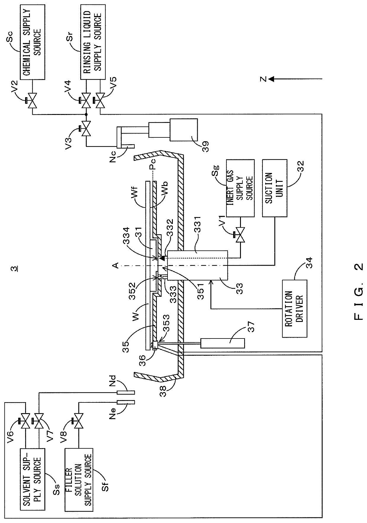
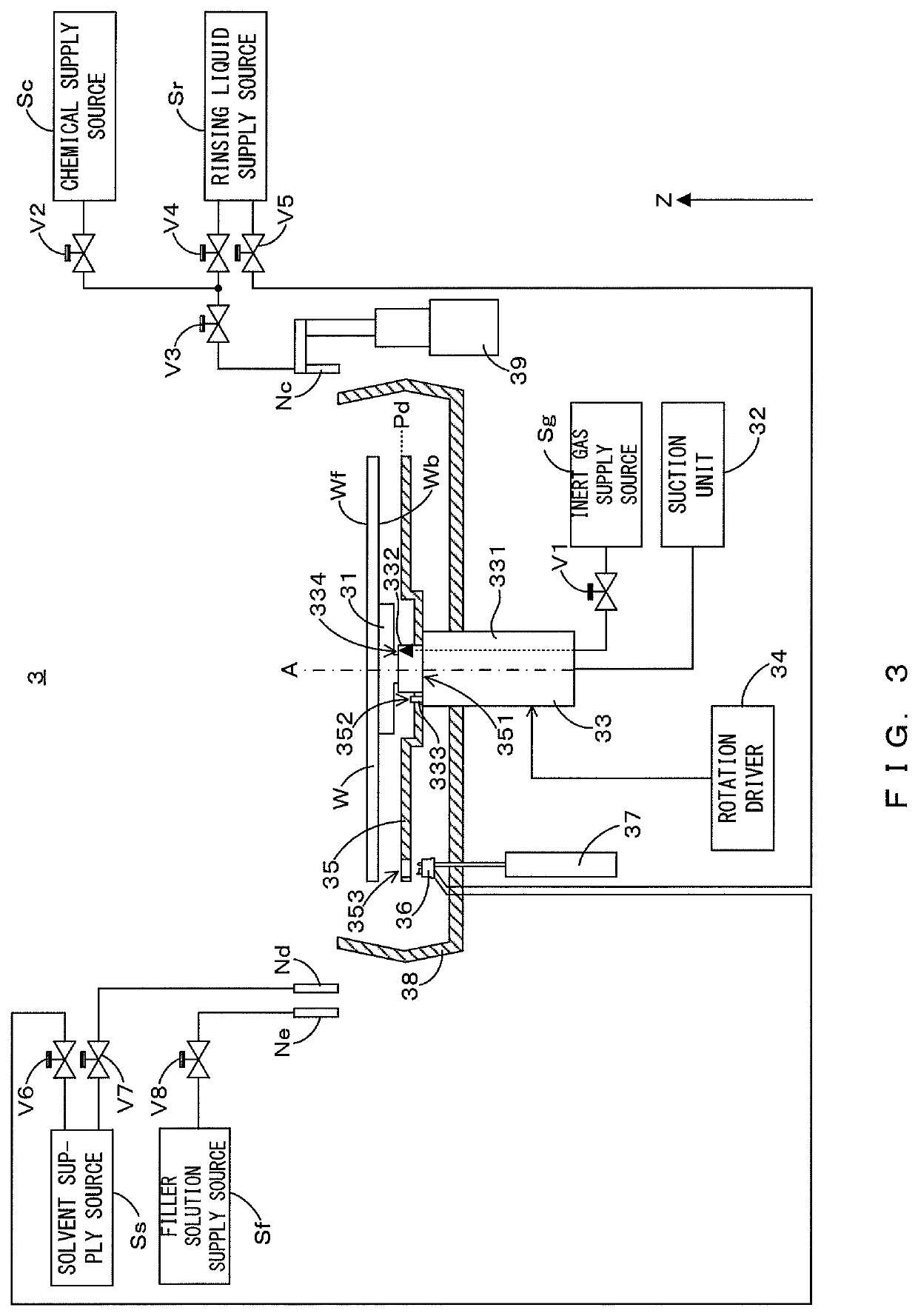
[0074]In the third embodiment, the upper nozzle Ng is further provided besides upper nozzles Nc, Nd and Ne and a nozzle driver 39 (see FIG. 2) is provided for the upper nozzle Ng. The nozzle driver 39 operates in response to a command from a controller 9, whereby the upper nozzle Ng moves between a gas supply position and a standby position. The gas supply position means a position separated upwardly from the central portion of the front surface Wf of the substrate W and the standby position means a position separated from a cup 38.

[0075]As shown in FIG. 10, an inert gas supply source Sg is connected to the upper nozzle Ng via a valve V9. Thus, when the controller 9 opens the valve V9, inert gas is supplied from the inert gas supply source Sg toward the central portion of the front surface Wf of the substrate W held by a spin chuck 31. In this way, the inert gas flows from a center toward a peripheral edge of the substrate W along the front surface Wf of the substrate W (see broken-...

first embodiment

[0079]Here, only the spin-off 2 process may be performed as in the However, depending on properties (viscosity, volatility, surface tension, solubility of solvent and filler, etc.) of the filler solution, a filling rate of the filler solution in the concave portions Wc may become nonuniform within the plane of the substrate W. Specifically, a centrifugal force generated by high-speed rotation of the substrate W increases from a central portion toward a peripheral edge portion of the substrate W. Particularly, in the peripheral edge portion, the filler solution having entered the concave portions Wc may be discharged from the concave portions Wc by the above centrifugal force. Thus, the filling rate may be reduced at the peripheral edge portion. If a baking process is, for example, performed with the filling rate remaining to be nonuniform in this way, stresses acting on the concave portions Wc are biased in the peripheral edge portion due to the shrinkage of the filler solution. Fu...


PUM

PropertyMeasurementUnit
diameteraaaaaaaaaa
rotational speedaaaaaaaaaa
flexibleaaaaaaaaaa

Abstract

A substrate processing method comprises: a liquid film forming step of forming a liquid film of a rinsing liquid on a pattern forming surface of a substrate formed with a pattern; a liquid pool forming step of forming a liquid pool of an organic solvent by supplying the organic solvent to the liquid film near a center of rotation of the substrate; a replacement step of replacing the rinsing liquid constituting the liquid film with the organic solvent by supplying the organic solvent to the liquid pool while rotating the substrate at a rotational speed higher than in the liquid pool forming step; an application step of applying a filler solution to the pattern forming surface coated with the organic solvent; and a filling step of causing a filler contained in the filler solution and applied to the pattern forming surface to sink and filling concave portions of the pattern with the filler.

Description

CROSS REFERENCE TO RELATED APPLICATION[0001]This application claims benefit of priority to Japanese Patent Applications enumerated below, the entire content of which is incorporated herein by reference:[0002]No. 2016-188638 filed Sep. 27, 2016; and[0003]No. 2017-153163 filed Aug. 8, 2017.BACKGROUND OF THE INVENTION1. Field of the Invention[0004]This invention relates to a substrate processing technique for processing a substrate formed with a pattern on a surface. Note that substrates include various substrates such as glass substrates for liquid crystal display, semiconductor substrates, glass substrates for PDP, glass substrates for photo mask, substrates for color filter, substrates for recoding disc, substrates for solar cell, substrates for precision electronic device including substrates for electronic paper, rectangular glass substrates, flexible substrates for film liquid crystal or substrates for organic EL.2. Description of the Related Art[0005]A manufacturing process of a...

Claims


Application Information

Patent Timeline
Patent Type & Authority Patents(United States)
IPC IPC(8): B05D3/12H01L21/06B05D3/00B05D1/00H01L21/02H01L21/67
CPCH01L21/06B05D1/002H01L21/02057B05D3/002H01L21/6715H01L21/67051
Inventor KANEMATSU, YASUNORI
Owner DAINIPPON SCREEN MTG CO LTD
Why Eureka
Try Eureka