
Linear movement type reaction treatment apparatus and method thereof

a reaction treatment and linear movement technology, applied in the field of linear movement type reaction treatment apparatus and a method, can solve the problems of degrading the working efficiency in time, the complex movement mechanism or control, and the degrading of the working efficiency in spa

Active Publication Date: 2020-09-15
UNIVERSAL BIO RESEARCH CO LTD
View PDF17 Cites 2 Cited by
  • Summary
  • Abstract
  • Description
  • Claims
  • Application Information

AI Technical Summary

Benefits of technology

[0124]According to the first, seventeenth, eighteenth, or twenty-third invention, the reaction container, the liquid storage portion, and the sample storage portion used for the treatment are arranged in a linear shape. Accordingly, since the treatment including the pre-treatment may be performed consistently just by the movement of the dispensing head in the linear arrangement direction, the movement path of the dispensing tip is simplified, and the control is easy. Further, since the movement distance is the shortest, the treatment including the pre-treatment may be immediately and efficiently performed. Further, the burden of the user may be reduced. In addition, since the movement path is simplified, the cross-contamination may be reliably prevented by separating the movement paths of the corresponding samples. Since an ultrasonic vibration is applied to the sample, the extraction of the target material obtained from the sample and the homogenization and the suspension of the sample may be promoted. Then, since the reaction is promoted, the treatment may be immediately and efficiently performed. Further, the reliability of the treatment may be improved.
[0125]According to the second or eighteenth invention, the exclusive region is set as two or more exclusive regions so that one set of dispensing tip enters and the other sets of dispensing tips do not enter. Further, the reaction container and the like are arranged in a linear shape, and the movement of each set of the dispensing tips is limited as the movement in the linear arrangement direction by control. Accordingly, it is possible to reliably prevent the cross-contamination among the exclusive region. Further, since a separation unit including a unit necessary for the pre-treatment is provided in each exclusive region, the treatment may be consistently performed within each exclusive region, and hence the cross-contamination may be further reliably prevented.
[0126]According to the third or nineteenth invention, since the crossing head is provided so as to cross the entire exclusive regions in a relatively movable manner, this configuration is suitable for a case where a common reagent which is not suitably prepacked in the liquid storage portion of the plurality of exclusive regions and corresponds to, for example, a reagent to be heated or cooled necessarily or a reagent to be degraded in time easily is stored and supplied to the liquid storage portion or a case where a product, a produced material, or a result obtained in each exclusive region is stored and kept in a region separated from the exclusive region.
[0127]According to the fourth invention, since at least a part of the liquid storage portions is used as the prepacked storage portion sealed by the punchable film and storing a magnetic particle suspension or a solution necessary for the treatment in advance, there is no need to dispense the solution or the magnetic particle suspension to an empty liquid storage portion during treatment. Furthermore, since the punching tip located at a position in the linear arrangement direction is attached to the dispensing head for the punching operation and the dispensing tip is attached to the dispensing head after the detachment of the punching tip, it is possible to immediately perform treatment with high precision.
[0128]According to the fifth invention, since the sample storage portion support base is provided so as to support the sample storage portion in a vibratile manner, it is possible to prevent the propagation of the ultrasonic vibration to a portion other than the sample storage portion to be subjected to the ultrasonic vibration, and hence to efficiently apply the ultrasonic vibration to the sample storage portion.
[0129]According to the sixth or twentieth invention, since the sample is stored in the sample storage portion and the opening portion thereof is closed by the scattering prevention lid, it is possible to prevent the sample from being scattered in a vibration state, and hence to prevent the contamination of the sample in a portion other than the sample storage portion. Since the lid is punched and the sample therein is taken out by being suctioned with the dispensing tip after the vibration is applied to the sample, there is no need to open the lid by the user. Thus, it is possible to reduce a burden of the user and to prevent the contamination to the user. Further, since there is no need to attach the lid in a detachable state, the lid may be stably and safely attached so that the lid is not separated due to the vibration or the like.

Problems solved by technology

As a result, there is a concern that a movement mechanism or control becomes complex.
Further, there is a problem in that the working efficiency in space may be degraded.
As a result, a problem also arises in that the working efficiency in time may be degraded.
For this reason, the working efficiency in time is degraded or an enough reaction between the target material and the reagent may not be performed.
As a result, a problem arises in that the reaction treatment may not be performed with high reliability and efficiency.
In this way, when the steps are manually performed, a user feels a big burden.
Particularly, when each nucleic acid extracted from a plurality of samples (specimens) is handled, amplification treatment is needed, and a trouble further increases.
Further, there is a concern that the working area may be widened further.

Method used


Image

  • Linear movement type reaction treatment apparatus and method thereof
  • Linear movement type reaction treatment apparatus and method thereof
  • Linear movement type reaction treatment apparatus and method thereof

Examples


first embodiment

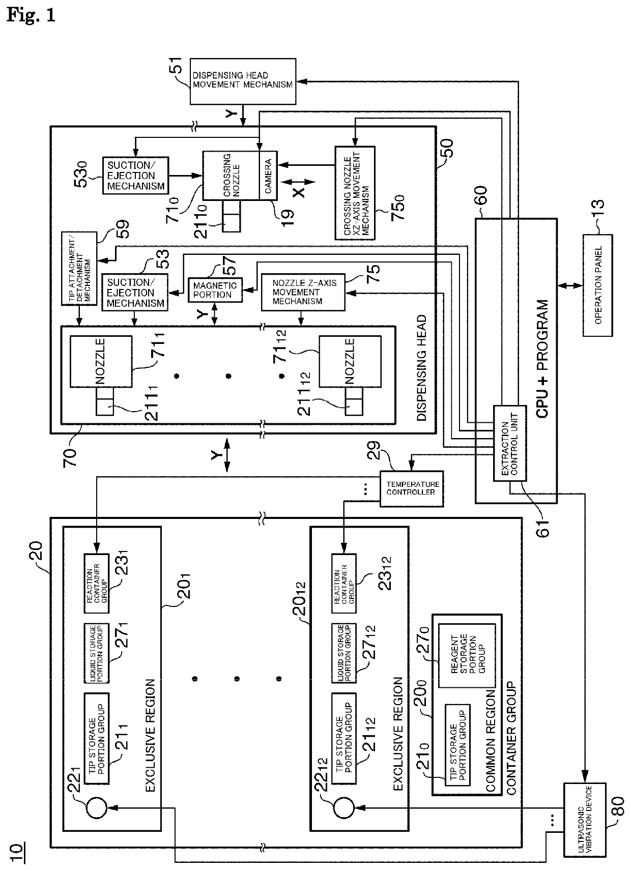
[0161]FIG. 1 is a block diagram illustrating a linear movement type reaction treatment apparatus 10 according to the invention.

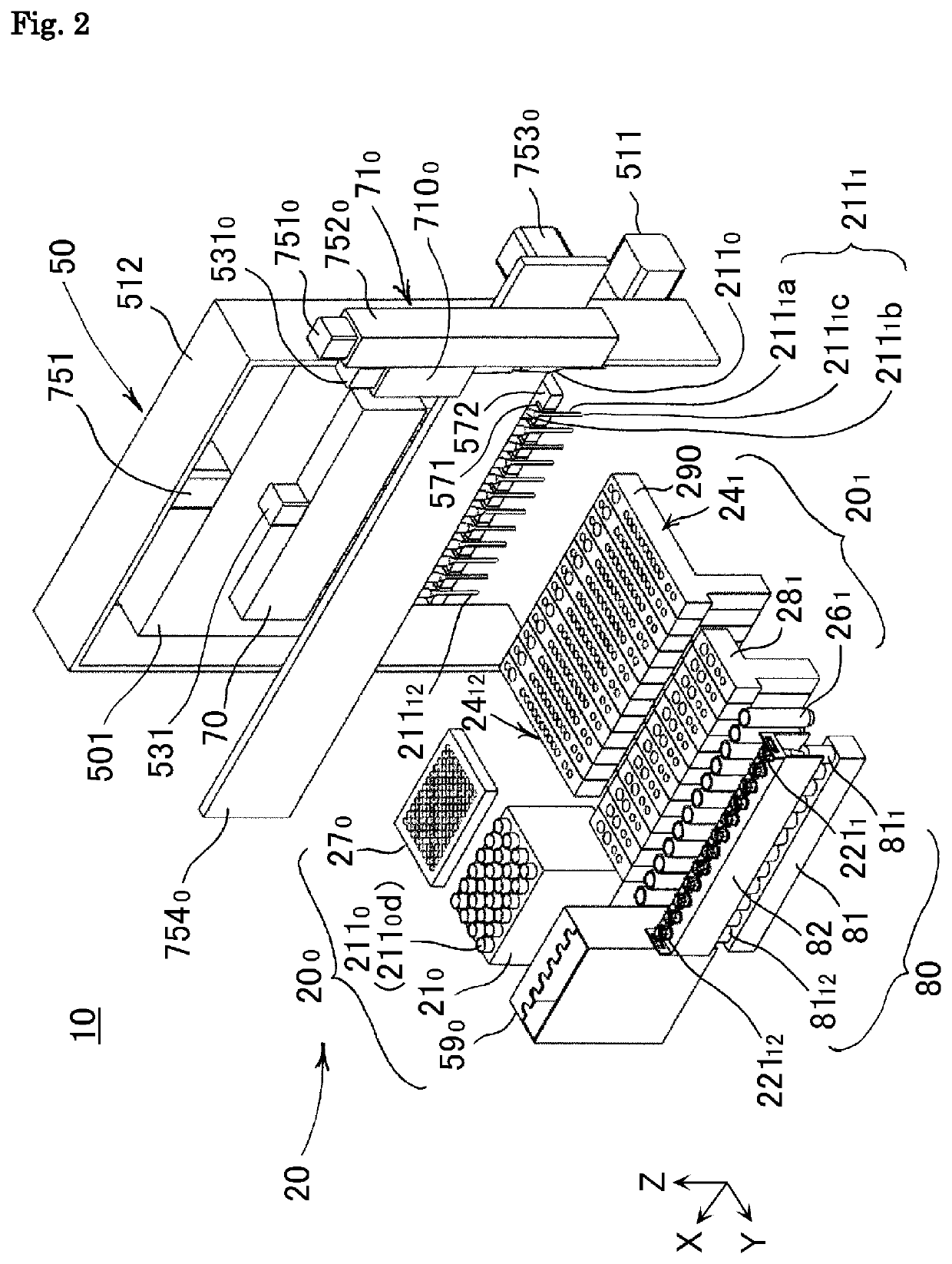
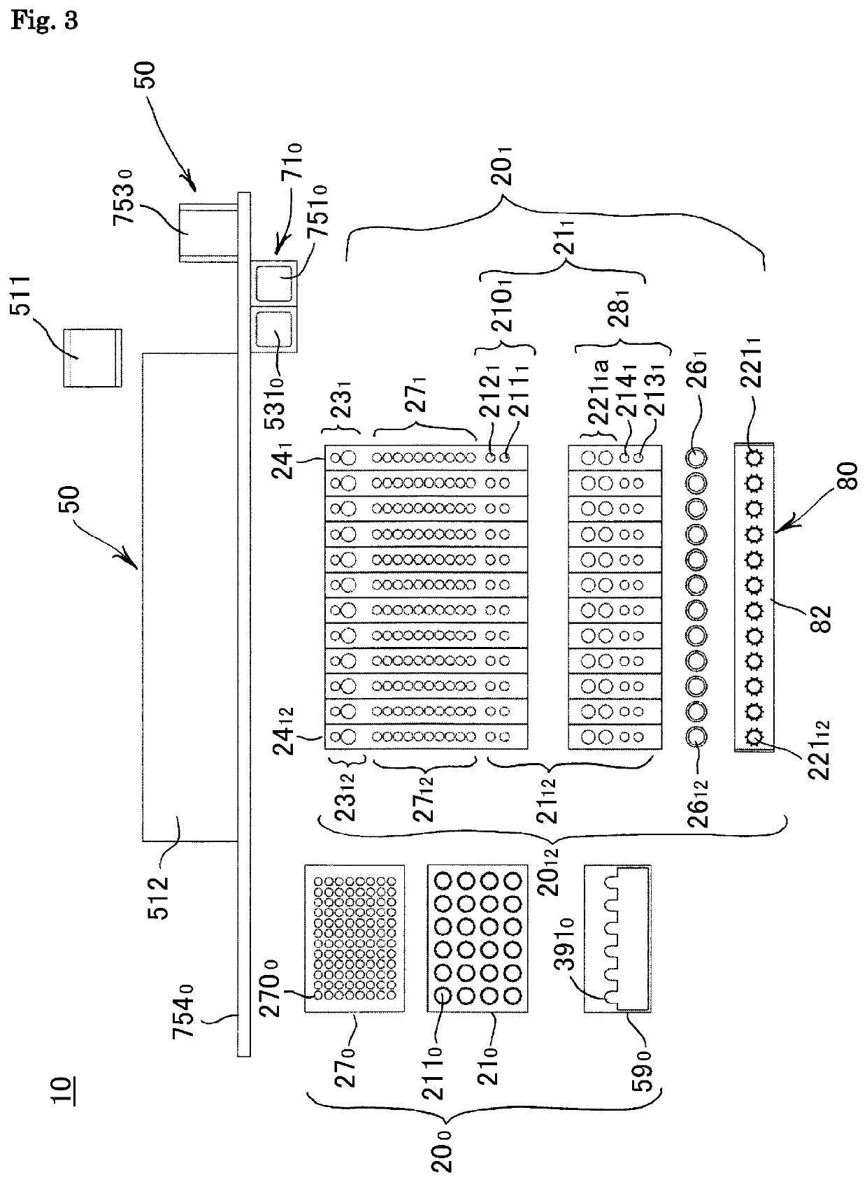
[0162]The linear movement type reaction treatment apparatus 10 includes a container group 20 that includes a plurality of (in this example, twelve) exclusive regions 20i (i=1, . . . , 12, omitted below) and a common region 200, a dispensing head 50 that includes a nozzle arrangement portion 70 in which a plurality of (in this example, twelve) nozzles 71i respectively and detachably equipped with dispensing tips 211i provided so that the front ends thereof are insertable into reaction containers respectively provided in the exclusive regions 20i and the liquid storage portions thereof and a crossing nozzle 710 which is movable so as to cross the entire exclusive region 20i and is detachably equipped with a dispensing tip 2110 provided so that the front end thereof is insertable into the liquid storage portions provided in the exclusive regions 20i and the com...


PUM

PropertyMeasurementUnit
temperatureaaaaaaaaaa

Abstract

An apparatus and related method to reliably prevent cross-contamination and to decrease working time or space involved with reaction treatment. The apparatus includes: a container group having one or more reaction containers and two or more liquid storage portions arranged in a linear shape; a dispensing head to which one or more dispensing tips insertable into the container group are detachably attached, the dispensing head being relatively movable with respect to the container group in a linear direction; a magnetic portion provided in the dispensing head and capable of: applying a magnetic field into each dispensing tip so that the magnetic particles are adsorbed to an inner wall of the dispensing tip, and removing the magnetic field so that the magnetic particles are resuspended in a solution; and an ultrasonic vibration device which applies ultrasonic vibration to a sample storage portion including at least one of the liquid storage portions.

Description

CROSS REFERENCE[0001]This application is a United States national phase application of co-pending international patent application number PCT / JP2013 / 081082, filed Nov. 18, 2013, which claims priority to Japanese patent application number 2012-252731, filed Nov. 16, 2012, the entire disclosures of which are hereby incorporated herein by reference.TECHNICAL FIELD[0002]The present invention relates to a linear movement type reaction treatment apparatus and a method thereof.BACKGROUND ART[0003]Hitherto, in treatment for a biological material such as DNA using magnetic particles, pre-treatment is performed first in a manner such that liquid storage portions are prepared as many as the number of treatment steps and a solution such as a reagent solution necessary for treatment is arranged while being dispensed from a reagent container every treatment. After the arrangement for the solution is completed, a solution stored in each liquid storage portion is suctioned or suctioned after being ...

Claims


Application Information

Patent Timeline
Patent Type & Authority Patents(United States)
IPC IPC(8): G01N35/00G01N21/64B01L7/00G01N35/10C12N15/10B01L3/00G01N35/04
CPCG01N35/00732G01N21/6452G01N35/0098G01N21/6428C12N15/1013B01L7/52G01N35/10B01L2300/044G01N2021/6439G01N2035/1053B01L3/5082G01N2035/00376B01L2300/1822G01N35/1065G01N2035/0412B01L2400/0439B01L2300/0861G01N35/1002B01L2200/0647
Inventor TAJIMA, HIDEJI
Owner UNIVERSAL BIO RESEARCH CO LTD
Learn More