
Transient stray voltage detector and system

a detector and transient technology, applied in short-circuit testing, measurement using digital techniques, instruments, etc., can solve the problems of reducing feed intake, reducing water intake, and difficulty in moving or handling animals

Active Publication Date: 2020-09-15
SALISBURY NOBLE M
View PDF8 Cites 0 Cited by
  • Summary
  • Abstract
  • Description
  • Claims
  • Application Information

AI Technical Summary

Benefits of technology

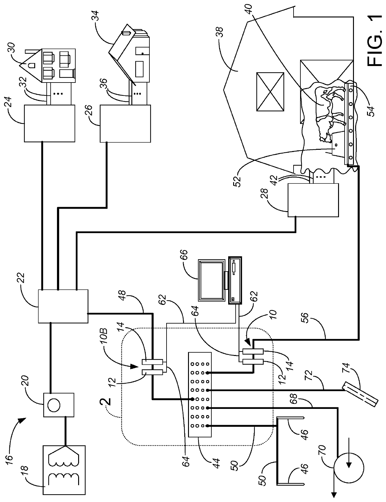
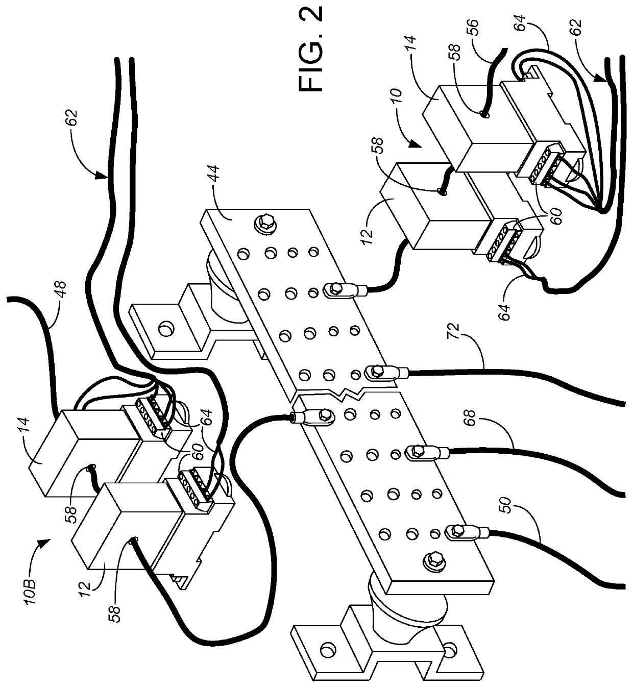
[0006]The present invention is a transient stray voltage detector as well as a system using a transient stray voltage detector and a method of monitoring stray voltage, based off of monitoring of current. The transient stray voltage detector is deployed on a new grounding wire connecting to the equi-potential ground plane on a farm, and preferably in a second location involving an existing grounding wire, both relative to the main service bond. In one aspect, the detector includes a first transducer providing an output signal indicating the magnitude of stray current carried by the new grounding wire, and a second, separate transducer providing an output signal indicating the direction of the stray voltage (for either direct and / or alternating stray voltages). The combination of the two transducers, referred to as a directional flow current transducer, has its output logged as a function of time, preferably allowing comparison with the output of the second directional flow current transducer, thereby allowing transient, directional and locational stray voltage / stray current problems to be better identified, understood and addressed.

Problems solved by technology

Livestock may avoid certain stray voltage / stray current exposure locations, which may result in a) reduced water intake that may result if annoying or painful exposure is required for animals to access watering devices; b) reduced feed intake that may result if annoying or painful exposure is required for animals to accesses feeding devices or locations, c) difficulty of moving or handling animals in areas of annoying or painful voltage / current exposure; or d) the release of stress hormones produced by contact with painful stimuli.
In general, however, existing guidelines, standards and patent solutions fail to acknowledge and adequately consider the transient and locational nature of stray voltage / current.
Many stray voltages are caused by utility companies, as they providing insufficient wiring for their electrical grid and use the earth to complete circuits.
Other stray voltages / stray currents are caused by improper wiring of the electrical system including an improper neutral-to-ground connection, by improperly using the grounding path to carry neutral current, and by short circuits or other electrical insulation problems in the electrical equipment on the farm.

Method used


Image

  • Transient stray voltage detector and system
  • Transient stray voltage detector and system

Examples


Embodiment Construction

[0010]In general terms, the invention involves adding a new grounding wire between the location(s) of interest / problem (such as from the bulk water tank or platform by a bulk water tank for the cows, establishing an equi-potential plane for the livestock) and a primary grounding location and service bond for the electrical system. A new sensing device, which will be referred to as a directional flow current transducer 10, is monitored to sense electrical flow within the new grounding wire, and thereby provide useful information assessing transient, directional and locational stray voltage / stray current issues.

[0011]The preferred directional flow current transducer 10 is provided by a combination of a loop-powered AC current transmitter 12 and an AC power transducer 14. The loop-powered AC current transmitter 12 is generally used to monitor the average current (which could be thought of as being in either or both directions), while the AC power transducer 14 is generally used to dete...


PUM


Abstract

A directional flow current transducer is used as a transient stray voltage detector including a first transducer providing an output signal indicating the magnitude of stray current carried by a new grounding wire, and a second, separate transducer providing an output signal indicating the direction of the stray voltage (for either direct and / or alternating stray voltages). The new grounding wire might be between an equi-potential plane of a concrete platform for watering livestock and a grounding bus bar for grounding the service bond of the main electrical service panel, at a significant distance from the watering platform. The output of the directional flow current transducer is recorded, stored and analyzed as a function of time. Preferably by allowing comparison with the output of a second directional flow current transducer, the system allows transient, directional and locational stray voltage / stray current problems to be better identified, understood and addressed.

Description

CROSS-REFERENCE TO RELATED APPLICATION(S)[0001]This application claims priority from Provisional Application No. 62 / 471,341, filed Mar. 14, 2017, entitled STRAY VOLTAGE DETECTION, MEASUREMENT AND LOGGING. The contents of Provisional Application No. 62 / 471,341 are incorporated by reference in entirety.BACKGROUND OF THE INVENTION[0002]The present application relates to stray voltage, and particularly to stray voltage as it affects livestock and the production of such livestock, such as the production of milk by cows on a dairy farm. Stray voltage is a small voltage, generally considered less than 10 V, which may exist between two locations or objects. Stray current is the current produced by stray voltage, generally less than 1 Amp if carried on a 10Ω circuit. When an animal connects the two locations or objects, electricity may flow through the body of the animal. Livestock may avoid certain stray voltage / stray current exposure locations, which may result in a) reduced water intake t...

Claims


Application Information

Patent Timeline
Patent Type & Authority Patents(United States)
IPC IPC(8): G01R31/50H02B1/20G01R31/52G01R19/02G01R19/25A01K29/00H02B1/03H02B1/16
CPCH02B1/03A01K29/00H02B1/16G01R31/52G01R31/50H02B1/20G01R19/02G01R19/2513
Inventor SALISBURY, NOBLE M.
Owner SALISBURY NOBLE M
Learn More