Sample introduction system

a technology of introduction system and sample, which is applied in the direction of instruments, measurement devices, scientific instruments, etc., to achieve the effect of preventing the inability of users to correct the position easily

Active Publication Date: 2020-09-29
SHIMADZU CORP
View PDF7 Cites 1 Cited by
  • Summary
  • Abstract
  • Description
  • Claims
  • Application Information

AI Technical Summary

Benefits of technology

[0024]According to the present invention, an incorrect adjustment of the position by users can be easily prevented in the process of calibrating the descent position of the sampling needle.

Problems solved by technology

However, it is often the case that the tip of the needle lowered from the position based on the initial value reaches a considerably displaced position from the center of the well designated on the plate, due to an incorrect placement of the plate on the sample rack (particularly, due to its inclination or the like in the horizontal plane).

Method used


Image

  • Sample introduction system
  • Sample introduction system
  • Sample introduction system

Examples


first embodiment

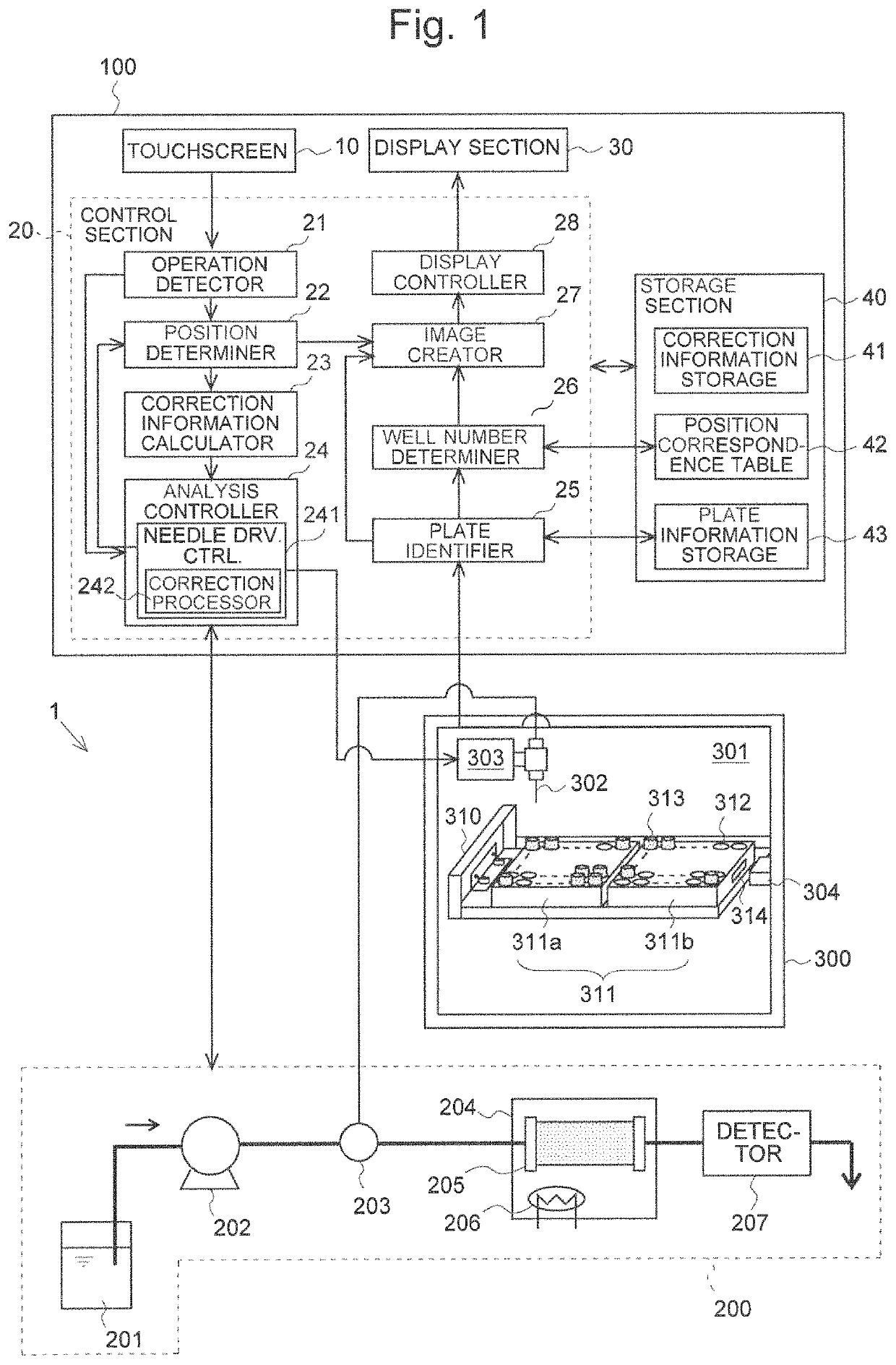
[0036]FIG. 1 is a block diagram showing a schematic configuration of a sample-analyzing system including a sample introduction system according to the first embodiment of the present invention. The sample-analyzing system 1 includes a controller 100, liquid chromatograph (LC) 200 and auto-sampler 300. Among these devices, the controller 100 and auto-sampler 300 constitute the system which corresponds to the sample introduction system of the present invention.

[0037]It should be noted that the LC 200 is one example of the analyzer in the present invention. The present invention allows the use of other types of analyzers, such as a liquid chromatograph mass spectrometer (LC-MS), gas chromatograph (GC), gas chromatograph mass spectrometer (GC-MS) or spectrophotometer.

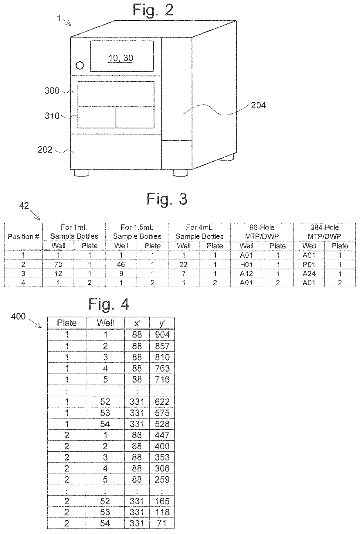
[0038]The sample-analyzing system 1 is realized as a single apparatus, as shown in FIG. 2. Alternatively, a control computer consisting of a workstation, personal computer (PC) or similar device may be externally coupled wi...

second embodiment

[0081]The system described in the first embodiment is configured to graphically present both the number Ni of each reference well Wi and its position on the plates 311a and 311b in the calibration process. As another embodiment, as shown in FIG. 8, the number Ni of the reference well Wi and that of the plate 311 may be displayed using characters on the display section 30a. In this embodiment, the image creator 27 described in the first embodiment is dispensable, since the calibration process assisting image 600 is not displayed. According to the present embodiment, even if the display section 30a is not fully capable of displaying graphical information, users can recognize the number Ni and position of the reference well Wi by character information. Additionally, in place of the GUI buttons 601-604 in the first embodiment, hardware buttons 10a as shown in FIG. 8 may be provided for the operation of moving the sampling needle 302.

third embodiment

[0082]As yet another embodiment, the display section in the present invention may be realized using an external device, as shown in FIG. 9. The display section 30b may be any display device having a screen on which the calibration process assisting image 600 can be displayed, such as a monitor offered with a personal computer (PC). In the present embodiment, the sample-analyzing system 1a is not a single apparatus; the system is composed of a PC 100a connected with the LC 200 and auto-sampler 300 via a network cable NW (or wireless LAN (local area network)). In this case, the operation section in the present invention should preferably be realized in the form of buttons or similar elements provided in the auto-sampler 300, although an input device offered with the PC 100a may alternatively be used as the operation section. The PC 100a only needs to have the functions of the image creator 27 and the display controller 28 described in the first embodiment; the other functions may be r...


PUM

PropertyMeasurementUnit
liquid chromatographaaaaaaaaaa
data structureaaaaaaaaaa
liquid chromatograph mass spectrometeraaaaaaaaaa

Abstract

Provided is a sample introduction system for sequentially introducing a plurality of samples into an analyzer 200, the system including: an auto-sampler 300 including a sampling needle 302 for suctioning a sample from each well 312 provided in a plate 311 placed on a sample rack 310 or from a sample container 313 placed in the well 312, and a needle drive mechanism 303 for driving the sampling needle 302 in horizontal and vertical directions; an operation section 10 for allowing a user to command the needle drive mechanism 303 to drive the sampling needle 302; and a display controller 28 for displaying, on a screen of a display section 30, an identification of the well 312 related to a reference point defined on the plate 311 in a correction process conducted by the user by manipulating the operation section 10 so as to operate the needle drive mechanism 303 so that the sampling needle 302 is transferred to a predetermined position serving as the reference point.

Description

[0001]This is a National Stage of International Application No. PCT / JP2014 / 063316 filed May 20, 2014, the contents of all of which are incorporated herein by reference in their entirety.TECHNICAL FIELD[0002]The present invention relates to a sample introduction system including an auto-sampler for sequentially introducing a plurality of samples into an analyzer for analyzing samples.BACKGROUND ART[0003]For example, when a plurality of samples are automatically analyzed using a liquid chromatograph, an auto-sampler is used to sequentially introduce those samples into the liquid chromatograph. The auto-sampler contains a sample rack on which one or more plates can be placed, with each plate having a plurality of wells (holes with a closed bottom) in each of which a sample container (e.g. vial) is to be set or a sample is directly placed. The auto-sampler collects a predetermined amount of sample from each of these wells in a previously specified order and injects it into a mobile-phas...

Claims


Application Information

Patent Timeline
Patent Type & Authority Patents(United States)
IPC IPC(8): G01N35/10G01N30/24G01N35/00
CPCG01N35/10G01N35/1011G01N35/00732G01N35/109G01N30/24G01N2035/00801G01N2035/00891G01N2035/00831G01N2035/0091
Inventor MIDORIKAWA, YUSUKE
Owner SHIMADZU CORP
Why Eureka
Try Eureka