

Pressing device for tire-building machines
- Summary
- Abstract
- Description
- Claims
- Application Information
AI Technical Summary
Benefits of technology
Problems solved by technology
Method used
Image

Examples
Embodiment Construction
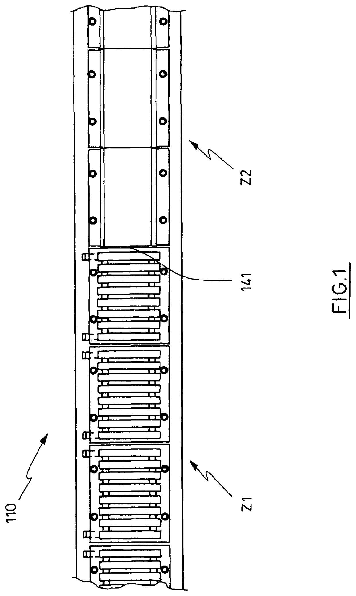
[0040]FIG. 1 shows the region adjacent to two zones (Z1, Z2) of a pressure-roller axle (110) having the resulting zone contact point (141) in a sectional illustration. The force-impinging devices of the zones are illustrated in an exemplary manner.
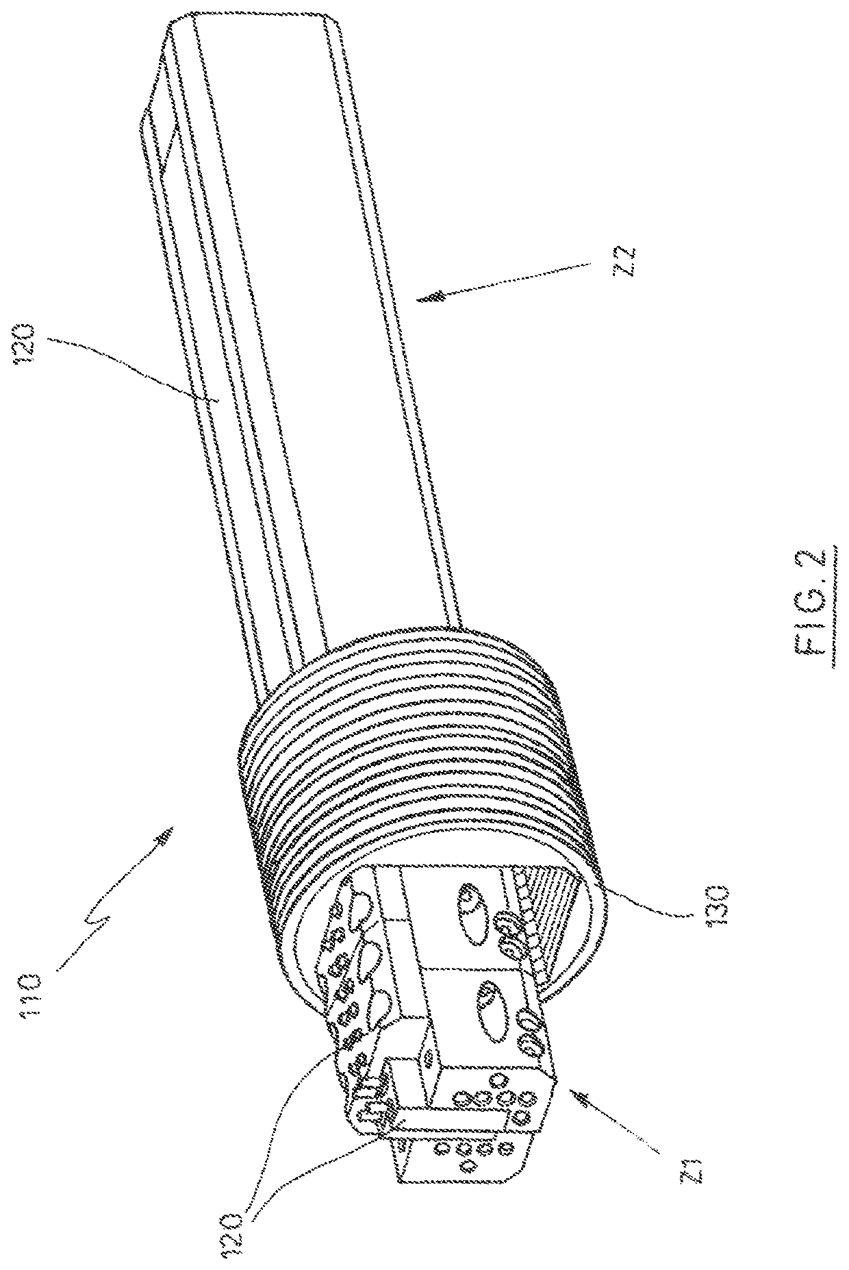
[0041]FIG. 2 shows two zones (Z1, Z2) of a pressure-roller axle (110) in a perspective illustration, having different force-impinging devices (120), and the illustration of a few disk elements (130) that are depicted in an exemplary manner. The cross section of the pressure-roller axle (110) in this exemplary embodiment is embodied so as to be rectangular having chamfered edges.
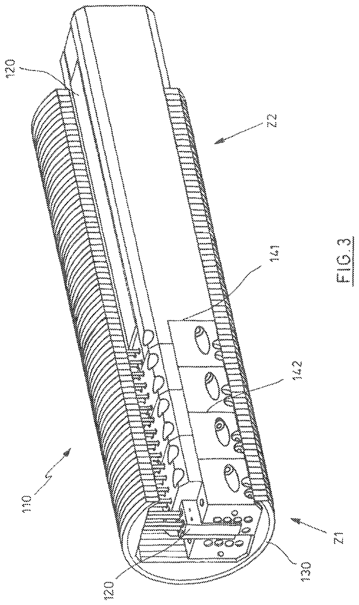
[0042]FIG. 3 shows two zones (Z1, Z2) of a pressure-roller axle (110) in a perspective illustration, having different force-impinging devices (120) and a multiplicity of disk elements (130) in a terminal position following the impingement with force by way of at least one part of the force-impinging devices (120) provided.
[0043]FIG. 4 in an exemplary manner depicts ...
PUM
 Abstract
Description
Claims
Application Information