Control of aftertreatment of an internal combustion engine

a technology of aftertreatment and internal combustion engine, which is applied in the direction of exhaust treatment, membrane filter, dispersed particle filtration, etc., can solve the problems of increasing the complexity of the aftertreatment system to meet the automotive emission legislation targets, the difficulty of packaging the temperature sensing means, and the large number of sensors required for thermal, so as to reduce the number of temperature sensor signals that must be analysed, the difficulty of reducing the number of temperature sensing means, and the effect of reducing the difficulty o

Active Publication Date: 2020-10-06
JAGUAR LAND ROVER LTD
View PDF6 Cites 0 Cited by
  • Summary
  • Abstract
  • Description
  • Claims
  • Application Information

AI Technical Summary

Benefits of technology

[0009]This provides the advantage that the number of sensors used to monitor an internal combustion after-treatment system may be reduced. It also provides an improved response time to changes in second temperature of exhaust gases at a second location.
[0066]This provides the advantage that the number of temperature sensing means is reduced when compared to existing systems. Consequently, difficulties experienced in packaging the temperature sensing means are reduced. Also the number of temperature sensor signals that must be analyzed is reduced.

Problems solved by technology

Over the last two decades diesel after-treatment systems have become increasingly complex to meet automotive emission legislation targets.
A problem with existing systems is that the components are generally operated independently of each other.
This has resulted in a large number of sensors being required for thermal and chemical management of the system.
This has also meant that a large number of signals received from the sensors have had to be analyzed.
Additionally the temperature sensors have a low response time and accuracy.
Furthermore, from a diagnostics point of view, the sensors require complex monitoring functions and are an added cost to the system.
Additional problems include difficulty in ensuring an optimum fuel-urea consumption balance for NOx conversion between the LNT and the SCR.

Method used


Image

  • Control of aftertreatment of an internal combustion engine
  • Control of aftertreatment of an internal combustion engine
  • Control of aftertreatment of an internal combustion engine

Examples


Embodiment Construction

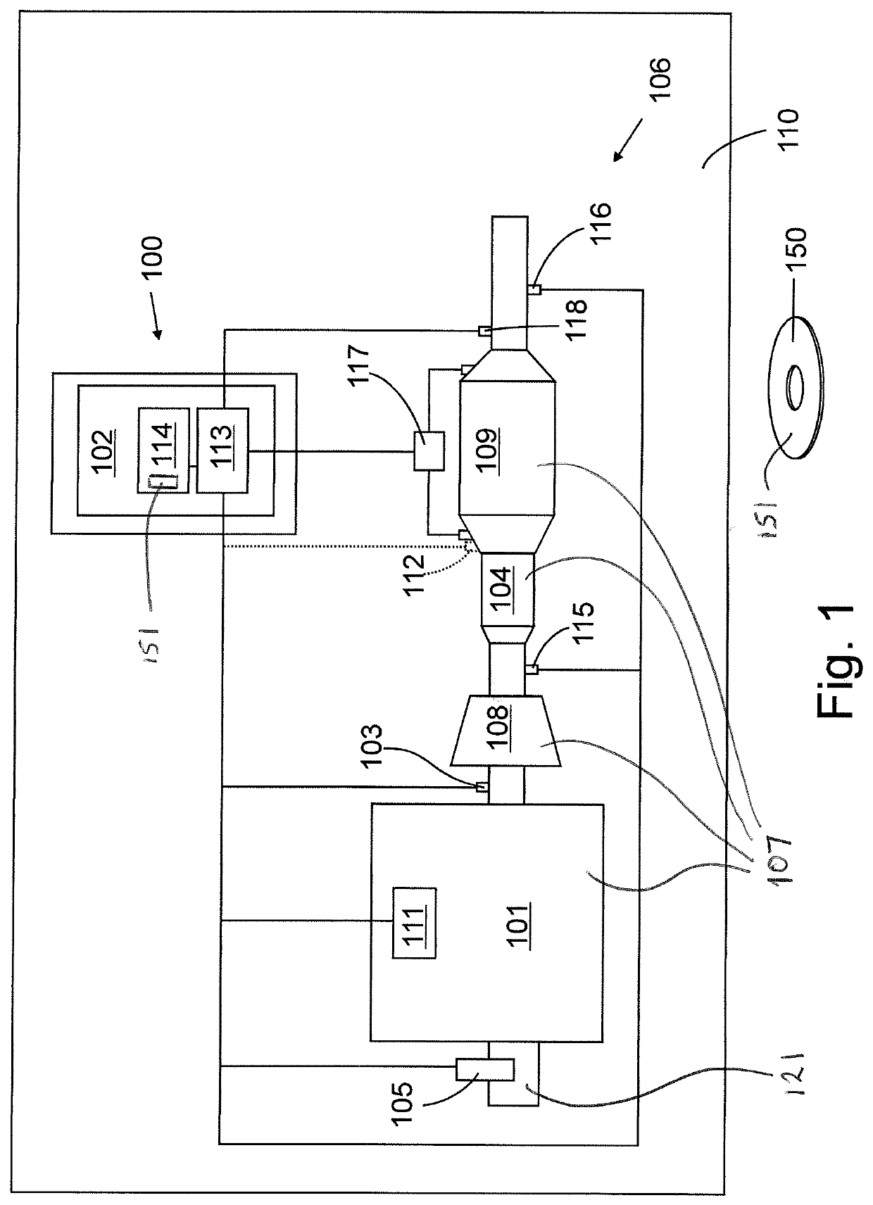
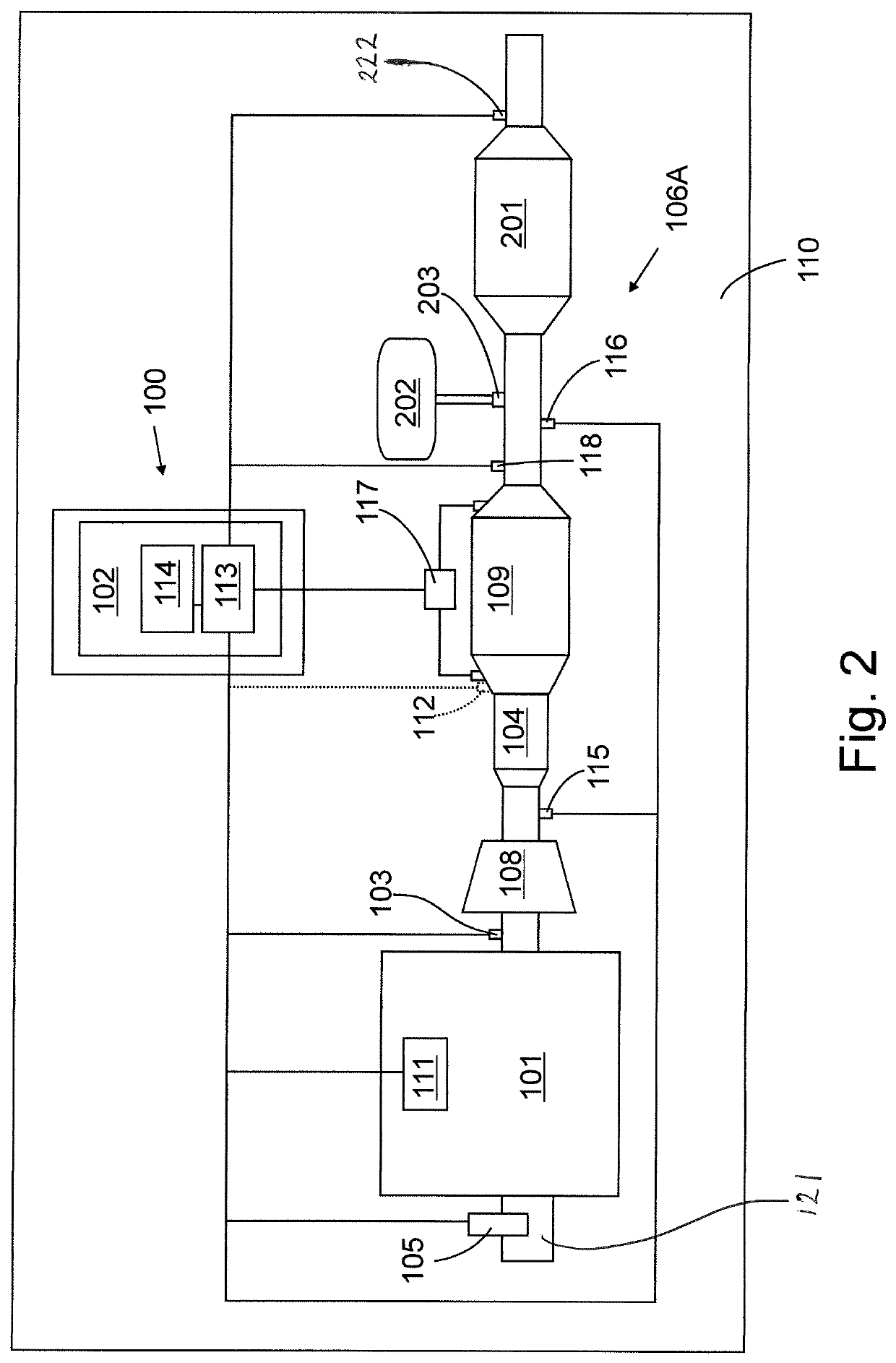
[0084]The Figures illustrate an apparatus 100 for controlling injection in an internal combustion engine 101, the apparatus 100 comprising a processing means 102 configured to: receive a first signal from a first temperature sensing means 103 indicative of a first temperature of exhaust gases outputted from an internal combustion engine 101 at a first location upstream of a first exhaust system component 104 configured to provide a passage for exhaust gases; receive a second signal from a flow rate sensing means 105 indicative of a flow rate of the exhaust gases outputted from an internal combustion engine; calculate an approximated value at least from the first signal and the second signal, the approximated value being indicative of a second temperature of exhaust gases at a location downstream of the first exhaust system component; and provide an output signal to control a rate of fuel injection, in dependence of the calculated approximated value.

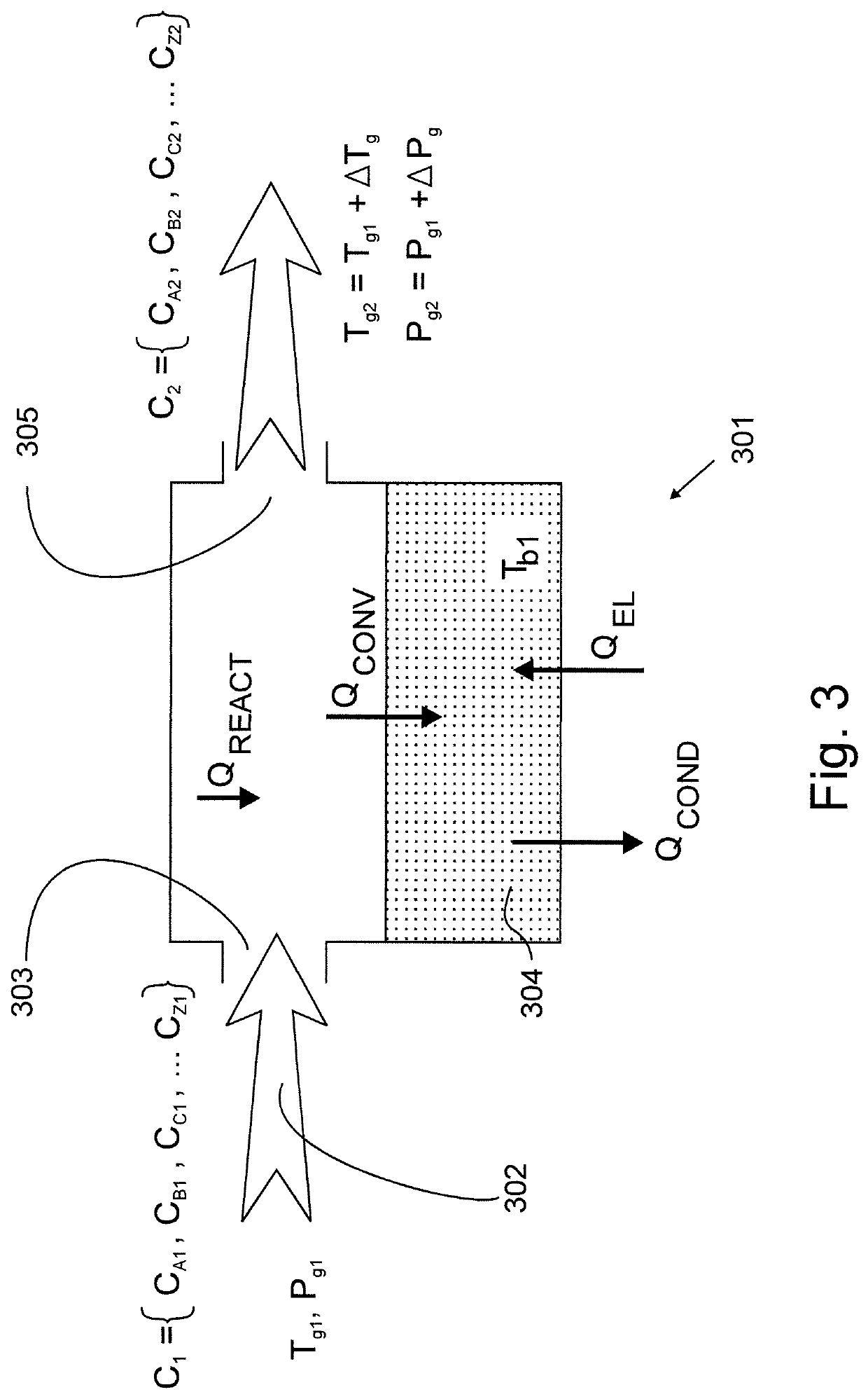
[0085]The approximated value may b...


PUM


Abstract

Apparatus (100) for controlling an aftertreatment system of an internal combustion engine (101), a system comprising an apparatus, a vehicle comprising a system and a method (1000) of controlling injection in an internal combustion engine (101) are disclosed. The apparatus comprises a processing means (102) configured to receive a first signal from a first temperature sensing means (103) indicative of a first temperature of exhaust gases outputted from an internal combustion engine (101) at a first location upstream of a first exhaust system component (104) configured to provide a passage for exhaust gases. The processing means is also configured to receive a second signal from a flow rate sensing means (105) indicative of a flow rate of the exhaust gases outputted from the engine (101) and calculate an approximated value at least from the first signal and the second signal. The approximated value is indicative of a second temperature of exhaust gases at a location downstream of the first exhaust system component (104). The processing means is further configured to provide an output signal to control the after treatment system, in dependence of the calculated approximated value.

Description

CROSS-REFERENCE TO RELATED APPLICATIONS[0001]This application is a 371 of International Application No. PCT / EP2017 / 056730, filed Mar. 21, 2017, which claims priority to GB Patent Application 1606583.1, filed Apr. 15, 2016, the contents of both of which are incorporated by reference herein in their entirety.TECHNICAL FIELD[0002]The present disclosure relates to control of aftertreatment of an internal combustion engine. In particular, but not exclusively it relates to control of aftertreatment of diesel engines in motor vehicles. Aspects of the invention relate to an apparatus, a system, a vehicle and a method.BACKGROUND[0003]Over the last two decades diesel after-treatment systems have become increasingly complex to meet automotive emission legislation targets. Systems have included several components, such as a diesel oxidation catalyst (DOC) for converting carbon monoxide and hydrocarbons to carbon dioxide, a diesel particulate filter (DPF) for filtering and burning soot, and a se...

Claims


Application Information

Patent Timeline
Patent Type & Authority Patents(United States)
IPC IPC(8): F01N9/00F02D41/02F02D41/30F01N3/035B01D53/94B01D46/00F01N3/025F01N3/021F01N3/20F01N3/10F01N3/08
CPCF01N3/0821F01N3/2066F01N3/021F01N9/007B01D53/9495F02D41/3005F01N3/035F01N3/0253B01D46/006F01N3/208F01N3/0814F02D41/0235B01D53/944B01D46/0027F01N9/005F01N9/002F01N9/00F01N3/103B01D53/9431F01N3/0842F01N2900/1606F01N2900/1404Y02T10/12F01N2900/1411B01D2279/30Y02T10/40Y02A50/20F01N11/005F01N2900/0601B01D46/80
Inventor BEVAN, NEILROMOCEA, ALEX
Owner JAGUAR LAND ROVER LTD
Why Eureka
Try Eureka