
Electric drive device and electric power steering device

a technology of electric power steering and drive device, which is applied in the direction of electrical steering, association with control/drive circuit, transportation and packaging, etc., can solve the problem of enlarging the axial length of the electric power steering device, and achieve the effect of shortening the axial siz

Active Publication Date: 2020-10-06
HITACHI ASTEMO LTD
View PDF26 Cites 1 Cited by
  • Summary
  • Abstract
  • Description
  • Claims
  • Application Information

AI Technical Summary

Benefits of technology

The present invention aims to provide a watertight cover for an electronic control part that suppresses fluctuations in internal pressure and prevents water from entering. The cover includes a waterproof breathable member that removes any air or water vapor that may enter the cover. Additionally, the invention ensures effective dissipation of heat generated by the power supply and conversion circuit parts by transferring the heat to the motor housing, which has a sufficient thermal capacity. The covering of the through hole by the watertight cover, in conjunction with the efficient heat dissipation, leads to a compact size for the electronic control part without the need for a heat sink member.

Problems solved by technology

The provision of the heat sink member leads to enlarging the axial length of the electric power steering device.
Moreover, since electrical components constituting the power supply circuit part and the power conversion circuit part generate a large quantity of heat, it is required to effectively dissipate the heat to the outside, especially when the electric power steering device is made compact.

Method used


Image

  • Electric drive device and electric power steering device
  • Electric drive device and electric power steering device
  • Electric drive device and electric power steering device

Examples


Embodiment Construction

[0031]The following details an embodiment of the present invention with reference to the drawings. However, the present invention is not limited to the embodiment, but includes various modifications and applications belonging to technical conception of the present invention.

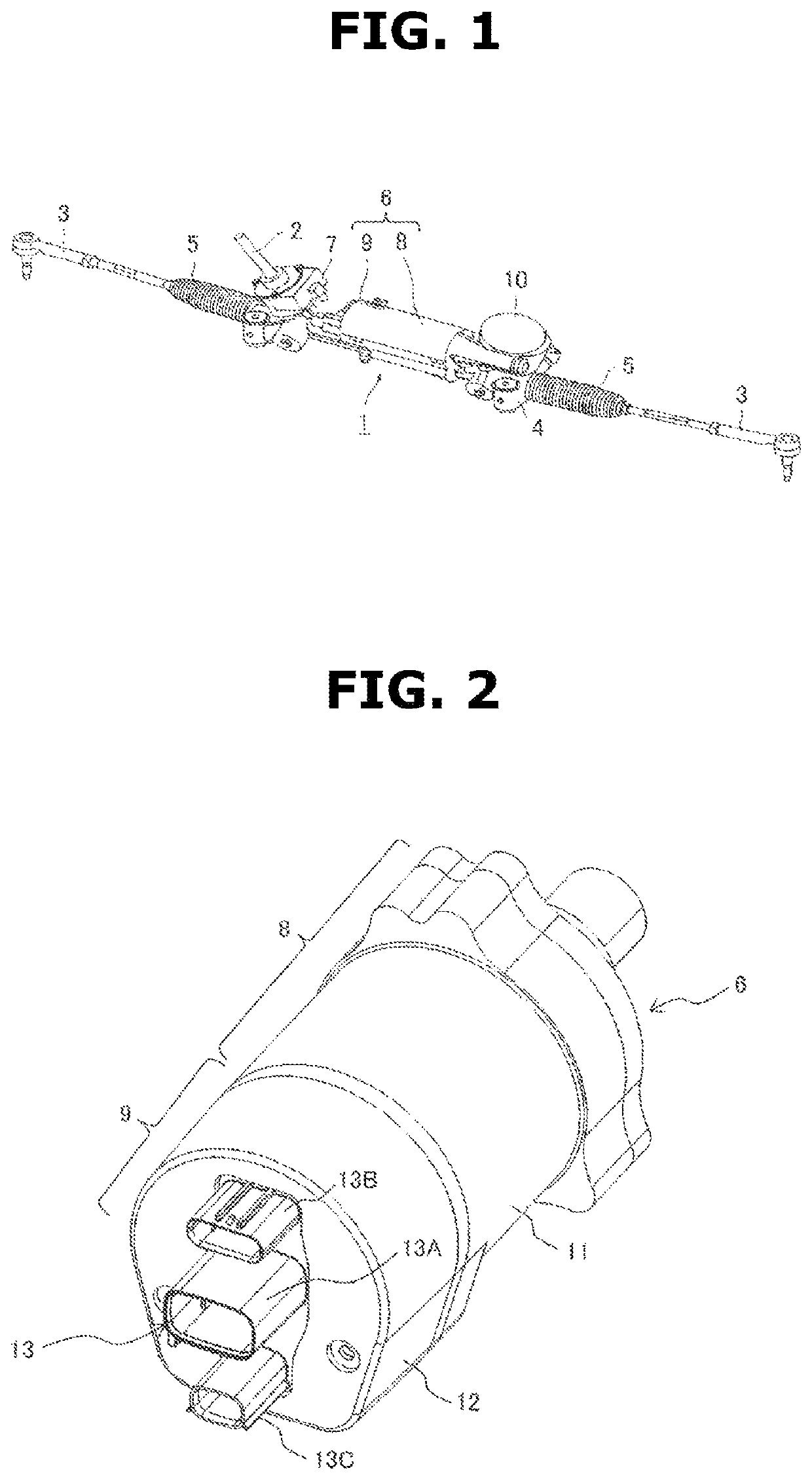
[0032]The following briefly describes configuration of a steering device as an example of device to which the present invention is applied, with reference to FIG. 1, prior to description of the embodiment of the present invention.

[0033]First, the following describes a steering device for steering front wheels of an automotive vehicle. Steering device 1 is configured as shown in FIG. 1. A steering shaft 2 is connected to a steering wheel not shown, and includes a lower end formed with a pinion not shown, wherein the pinion is in mesh with a rack not shown, wherein the rack extends in a vehicle body lateral direction. The rack includes ends linked to respective tie rods 3 for steering the front wheels leftward and ...


PUM


Abstract

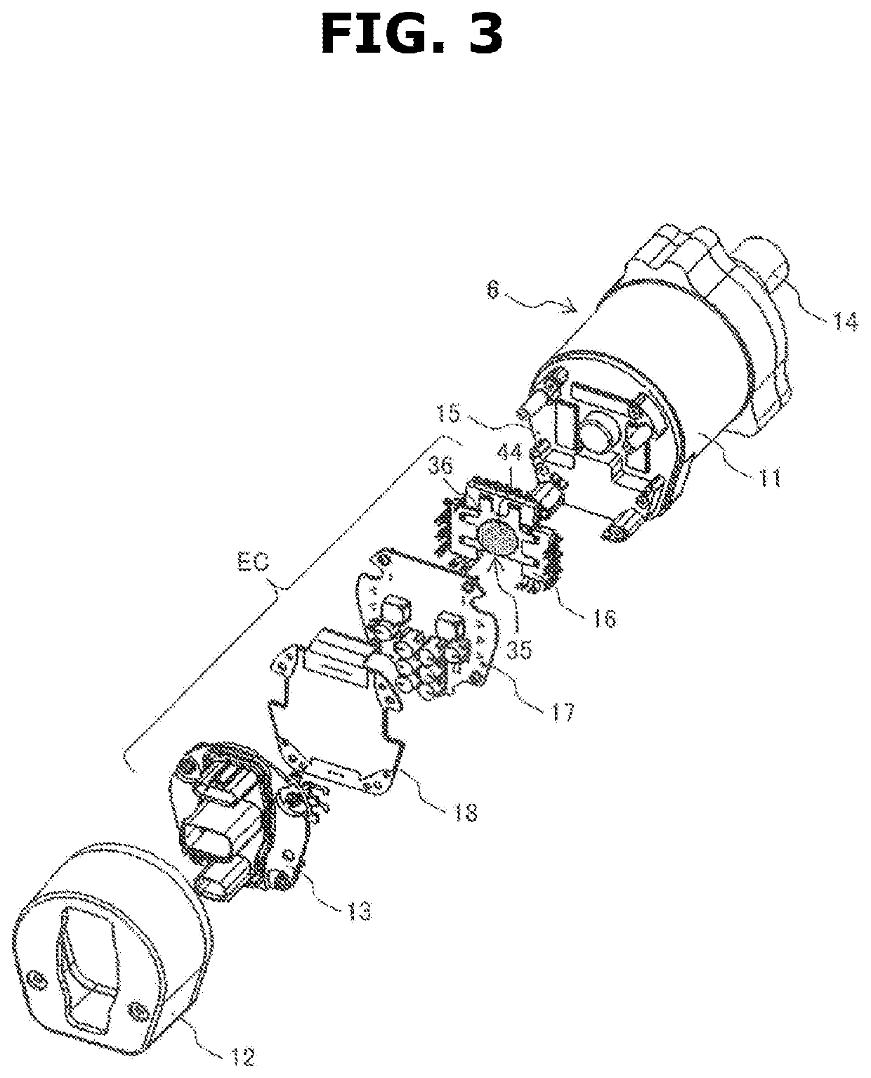
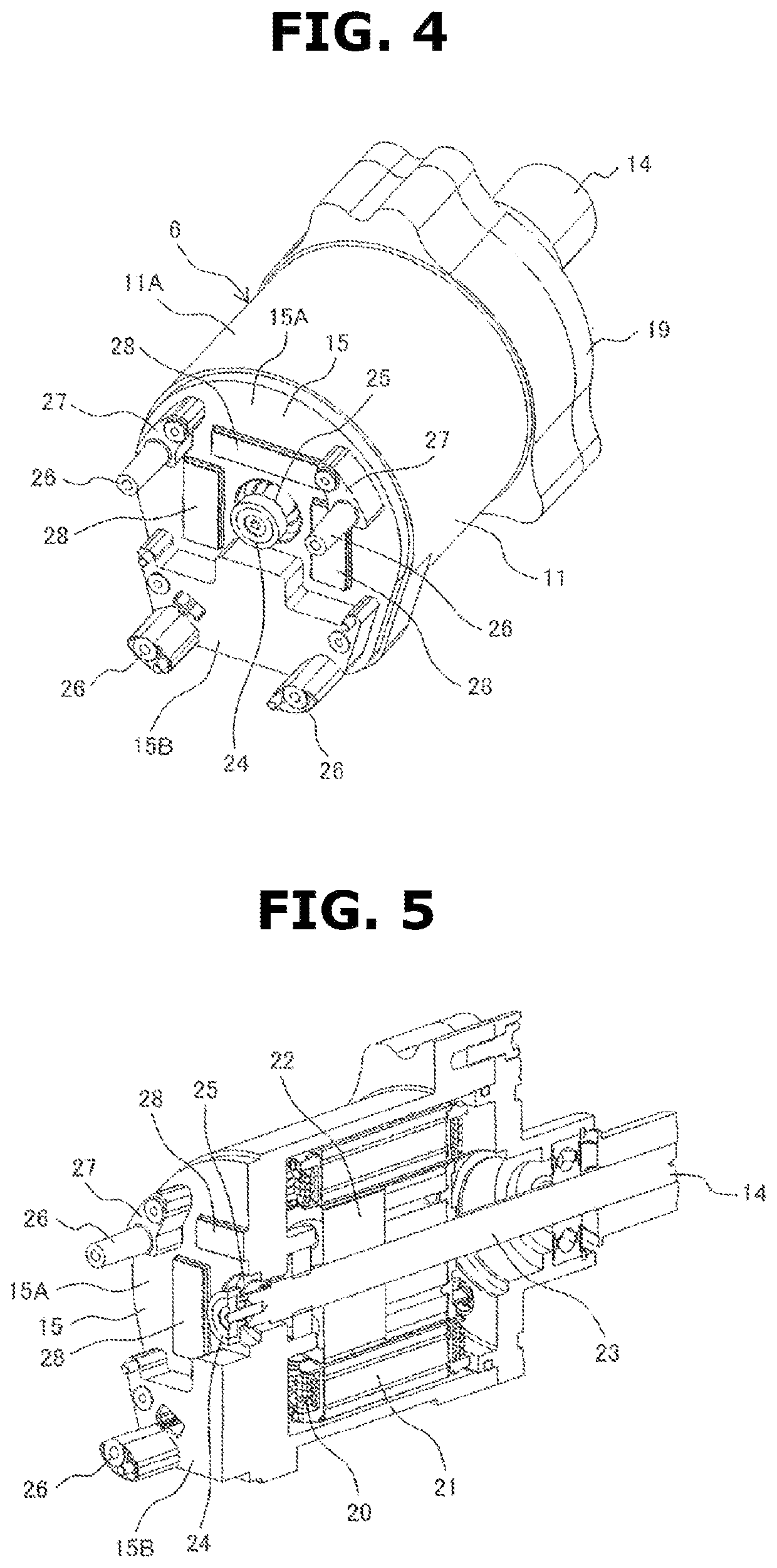
Provided is an electric drive device in which heat-dissipating sections (15A) (15B) that transfer at least heat generated by a power supply circuit unit (17) and power conversion circuit units (16) to a motor housing (11) are formed on an end surface section (15) of the motor housing (11) on the opposite side from an output section of a rotating shaft (23) of an electric motor. In addition, a watertight lid member (35) that covers a through hole (41) through which the rotating shaft passes and the end of the rotating shaft (23) from the exterior is attached to the end surface section (15) around the through hole (41), and a waterproof breathable membrane (44) that prevents the passage of moisture while allowing the passage of air and water vapor is provided to part of the watertight lid member.

Description

TECHNICAL FIELD[0001]The present invention relates generally to an electric drive device and an electric power steering device, and particularly to an electric drive device and an electric power steering device in which an electronic control unit is provided.BACKGROUND ART[0002]In a general field of industrial machinery, a controlled object of a mechanical system is driven by an electric motor. In recent years, employment of an electric drive device of mechatronical integration type has been started, wherein the electric drive device includes both of an electric motor and an electronic control unit in a package, and wherein the electronic control unit includes semiconductor elements and others for controlling rotational speed and torque of the electric motor.[0003]As an example of electric drive device of mechatronical integration type, an electric power steering device for an automotive vehicle includes an electric motor, and an electronic control unit (ECU) for controlling the ele...

Claims


Application Information

Patent Timeline
Patent Type & Authority Patents(United States)
IPC IPC(8): H02K5/10H02K11/00H02K5/22H02K9/22H02K11/33B62D5/04
CPCB62D5/046H02K11/33B62D5/0406H02K5/225H02K9/22H02K5/22H02K5/10H02K9/223H02K11/21H02K9/02H05K7/2089H02K2205/09
Inventor KANAZAWA, TAKUROHAMADA, KEIJIMOTODA, HARUAKI
Owner HITACHI ASTEMO LTD
Learn More