
Ignition coil for internal combustion engine

a technology of internal combustion engine and ignition coil, which is applied in the direction of electric ignition installation, mechanical equipment, machines/engines, etc., can solve the problems of resin inserting into the inside, and achieve the effect of suppressing internal pressure, suppressing internal pressure of the tower, and suppressing defects

Active Publication Date: 2020-05-05
DENSO CORP
View PDF3 Cites 0 Cited by
  • Summary
  • Abstract
  • Description
  • Claims
  • Application Information

AI Technical Summary

Benefits of technology

The present invention provides an improved structure of an ignition coil for an internal combustion engine that prevents leakage of resin during production and increases in internal pressure during the resin sealing process. The structure includes a high voltage tower shaped part with a vent part that allows air to escape during the resin sealing process, preventing the internal pressure from increasing and preventing leakage of resin. The technical effects of the invention are to improve the quality and reliability of the ignition coil for internal combustion engines.

Problems solved by technology

As a result, when a gap is formed between the opening end part of the tower shaped through hole and the high voltage cap during the resin supply step in production of the ignition coil, the inserted resin leaks into the inside of the tower shaped through hole through the generated gap.

Method used


Image

  • Ignition coil for internal combustion engine
  • Ignition coil for internal combustion engine
  • Ignition coil for internal combustion engine

Examples


first exemplary embodiment

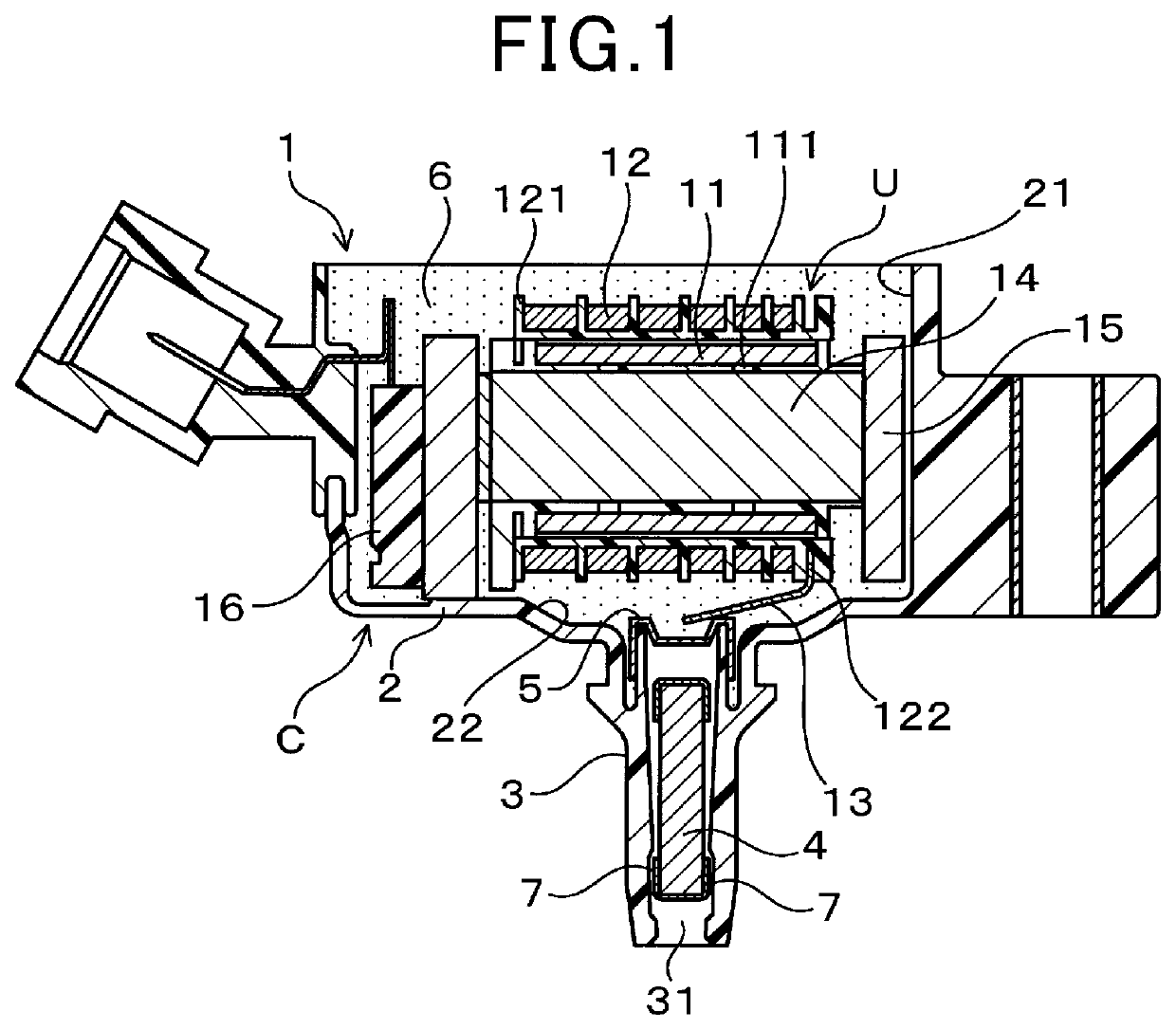
[0047]A description will be given of an ignition coil 1 a for an internal combustion engine according to the first exemplary embodiment of the present invention with reference to FIG. 1 to FIG. 13.

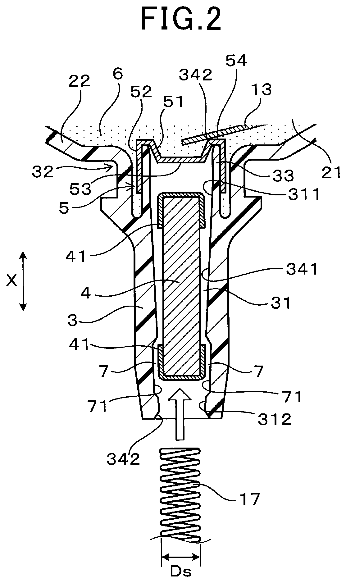
[0048]FIG. 1 is a view showing a cross section of the ignition coil 1 for an internal combustion engine according to the first exemplary embodiment of the present invention. FIG. 2 is a part enlarged view showing a cross section of the ignition coil 1 according to the first exemplary embodiment so as to assemble a coil spring 17 with a tower through hole 31.

[0049]As shown in FIG. 1 and FIG. 2, the ignition coil 1 according to the first exemplary embodiment has a primary coil 11, a secondary coil 12, a coil casing C, a resistance member 4 having a cylindrical shape, a high voltage cap 5 and an insulation resin member 6. The coil casing C has a casing body 2, an accommodating part 21 formed in the casing body 2 and a high voltage tower shaped part 3 having a cylindrical shape. The high volta...

second exemplary embodiment

[0111]A description will be given of the ignition coil 1 according to the second exemplary embodiment with reference to FIG. 14A, FIG. 14B, FIG. 14C to FIG. 17A to FIG. 17F.

[0112]FIG. 14A is a view showing an enlarged cross section of the high voltage tower shaped part 3 in the ignition coil 1 for an internal combustion engine according to the second exemplary embodiment of the present invention.

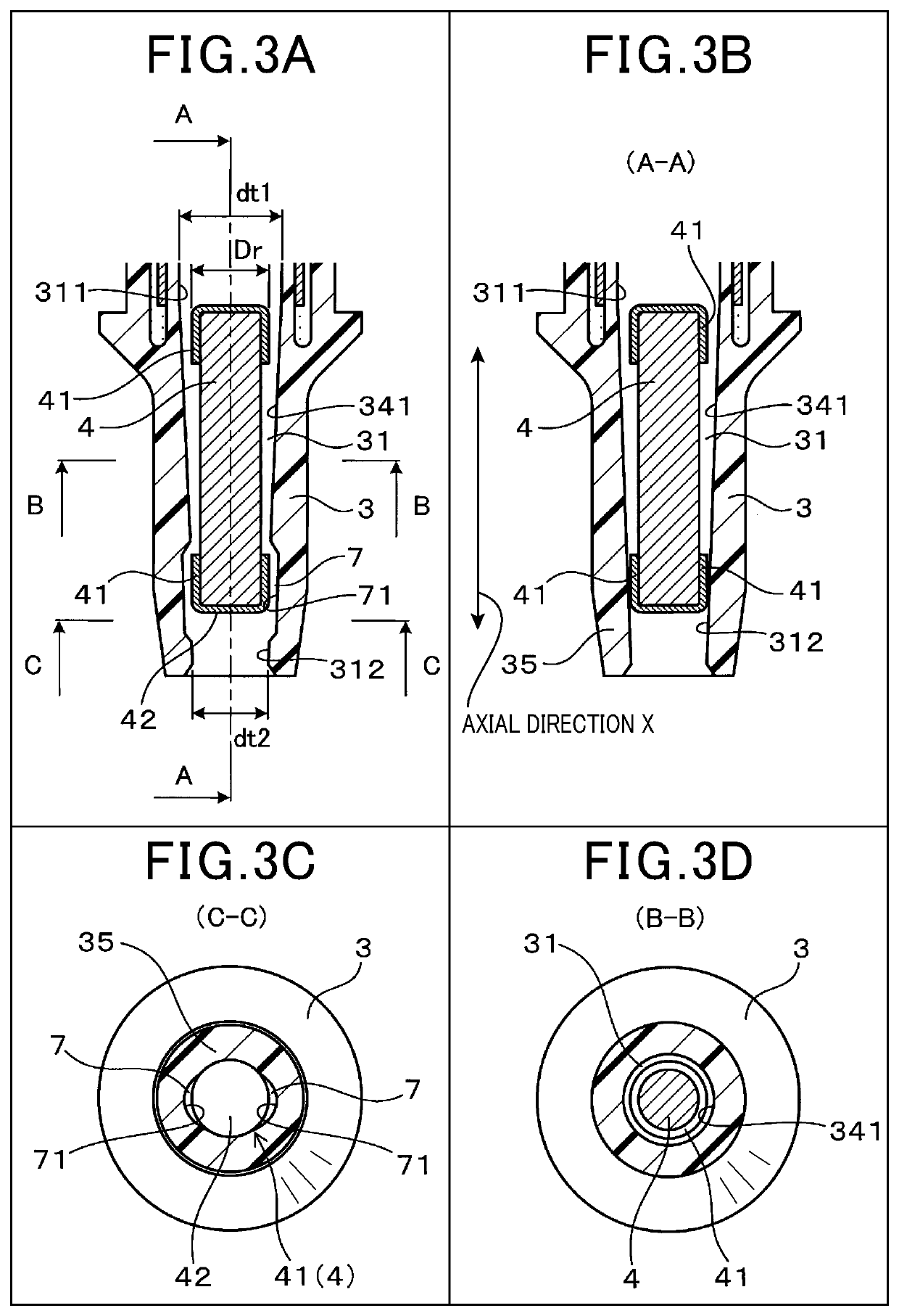
[0113]In the structure of the ignition coil 1 according to the first exemplary embodiment previously described, the vent parts 7 are formed by the grooves 71 formed in the tower through hole 31, i.e. on the inner peripheral surface of the high voltage tower shaped part 3.

[0114]However, the concept of the present invention is not limited by the structure of the ignition coil 1 according to the first exemplary embodiment.

[0115]As shown in FIG. 14A, the ignition coil 1 according to the second exemplary embodiment has the structure in which the vent parts 7 are formed between the outer periphera...


PUM

PropertyMeasurementUnit
pressureaaaaaaaaaa
atmospheric pressureaaaaaaaaaa
pressureaaaaaaaaaa

Abstract

An ignition coil has primary and secondary coils, a coil casing having a casing body, an accommodating part and a high voltage tower shaped part of a cylindrical shape, a resistance member arranged as a movable member in a tower through hole of the high voltage tower, a high voltage cap, and an insulation resin member with which the accommodating part is filled. A proximal end part of the tower through hole has an inner diameter which is greater than an outer diameter of a maximum outer diameter part of the resistance member. A distal end part of the tower through hole has an inner diameter which is less than the outer diameter of the maximum outer diameter part of the resistance member. A vent part is formed, through which the proximal end part of the tower through hole communicates with the distal end part of the tower through hole.

Description

CROSS-REFERENCE TO RELATED APPLICATION[0001]This application is related to and claims priority from Japanese Patent Application No. 2017-230848 filed on Nov. 30, 2017, the contents of which are hereby incorporated by reference.BACKGROUND OF THE INVENTION1. Field of the Invention[0002]The present invention relates to ignition coils to be mounted on ignition devices of internal combustion engines.2. Description of the Related Art[0003]In an ignition device for an internal combustion engine, an ignition coil generates a high voltage, and supplies the generated high voltage to a spark plug so as to generate an electric spark. In general, such an ignition coil has a primary coil, a secondary coil, and an outer peripheral core. The primary coil and the secondary coil are concentrically arranged around a central core, and the outer peripheral core is arranged outside of the primary coil and the secondary coil. The primary coil, the secondary coil and the outer peripheral core are accommoda...

Claims


Application Information

Patent Timeline
Patent Type & Authority Patents(United States)
IPC IPC(8): F02P3/02H01F38/12F02P9/00F02P3/055F02P13/00H01F27/30H01F27/02
CPCH01F38/12F02P13/00F02P3/055F02P9/002H01F27/306H01F27/022F02P3/02
Inventor KONDO, YUKI
Owner DENSO CORP
Learn More