Coupling device intended to couple a vehicle to a traction cable of a transportation installation

a technology of transportation installation and coupling device, which is applied in the direction of transportation and packaging, rope railways, mechanical equipment, etc., can solve the problems of high uncertainty on the position of the declutch roller, affecting the operation of the coupling device, and causing discomfort and inconvenience for users, so as to simplify the transportation installation and reduce the variation of the first position. , the effect of simplifying the transport installation

Active Publication Date: 2020-10-20
LST
View PDF5 Cites 0 Cited by
  • Summary
  • Abstract
  • Description
  • Claims
  • Application Information

AI Technical Summary

Benefits of technology

[0013]The technical problem underlying the invention therefore consists in providing a coupling device which is of simple and reliable structure, while allowing limiting the noise pollution generated during its opening and simplifying the structure of the declutch rails used to declutch the coupling device.
[0021]Such a configuration of the coupling device, and in particular such a sliding mounting of the actuation member on the support body, allows greatly reducing the variations of the first position of the actuation member, therefore of a declutch roller carried by the actuation member, according to the diameter of the traction cable portion clamped by the first and second clamping jaws. These arrangements allow using simpler and lower width declutch rails, and thus on the one hand simplifying the transport installation and on the other hand reducing the intensity of the impacts of the declutch roller against the declutch rail during the opening the coupling device. This results in a reduction of the noise pollution generated during the opening of the coupling device.
[0022]Such a mounting of the actuation member further ensures a displacement of the declutch roller carried by the actuation member along a rectilinear path, which allows greatly simplifying the structure of the clutch and declutch rails intended to cooperate with such a declutch roller.
[0026]According to an embodiment of the invention, the actuation member comprises at least one stop portion configured to cooperate with the support body when the actuation member is in the first stable position. These arrangements allow eliminating the variations of the first position of the actuation member, and therefore freezing the first position of the actuation member, regardless of the diameter of the traction cable portion clamped by the first and second clamping jaws. This results in the possibility of using declutch rails even simpler and of a width close to the diameter of the clutch roller carried by the actuation member, and therefore of further reducing the intensity of the impacts of the declutch roller against the declutch rail and the noise pollution generated during the opening of the coupling device.

Problems solved by technology

This therefore results in a high incertitude on the position of the declutch roller at the end station entrance.
However, the use of such a declutch rail induces, during the opening of the coupling device, impacts of the declutch roller against the declutch rail which are likely in long term to impair the operation of the coupling device.
Furthermore, such impacts are a source of discomfort and inconvenience for the users.
Furthermore, the use of such a declutch rail complicates the transport installation.

Method used


Image

  • Coupling device intended to couple a vehicle to a traction cable of a transportation installation
  • Coupling device intended to couple a vehicle to a traction cable of a transportation installation
  • Coupling device intended to couple a vehicle to a traction cable of a transportation installation

Examples


Embodiment Construction

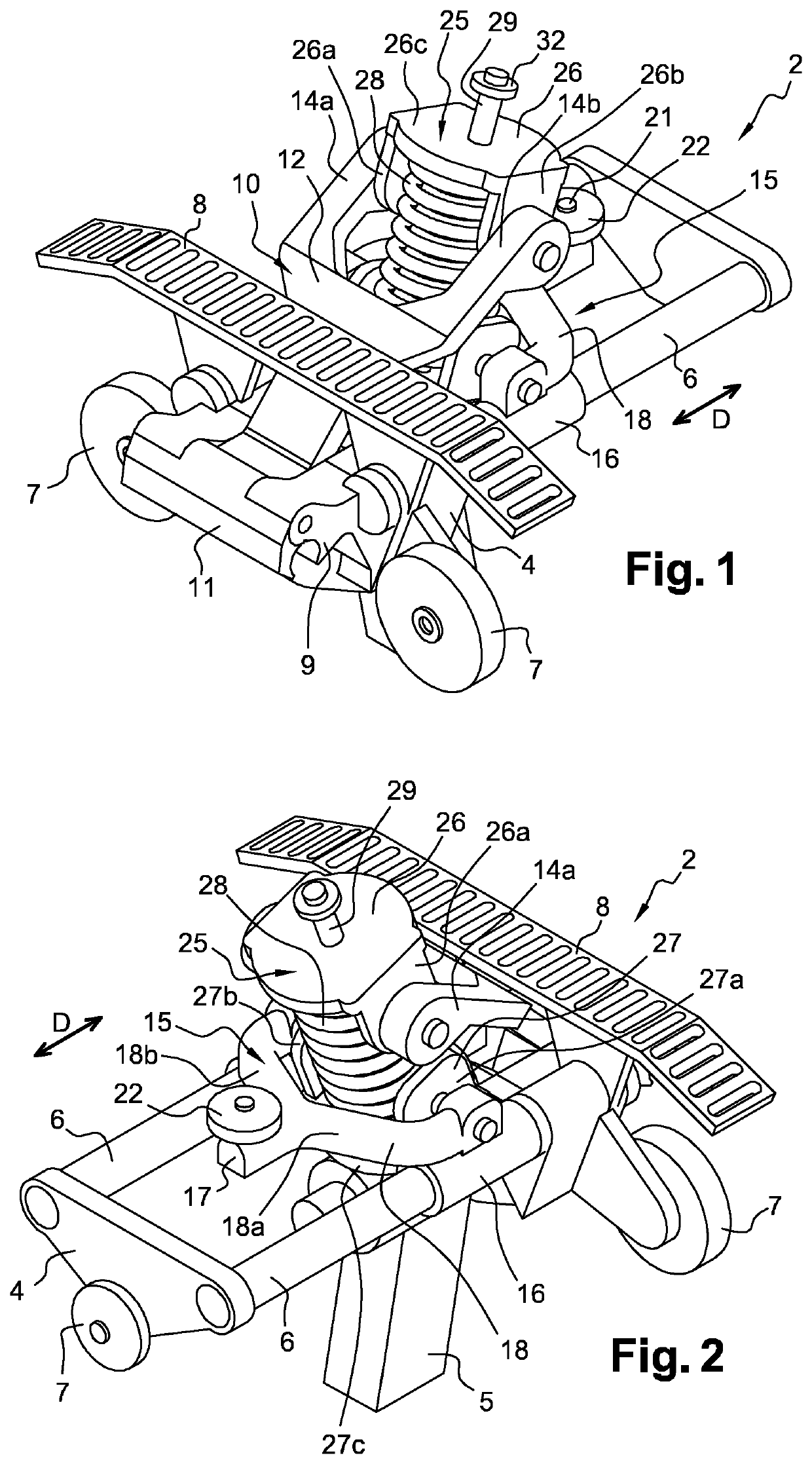
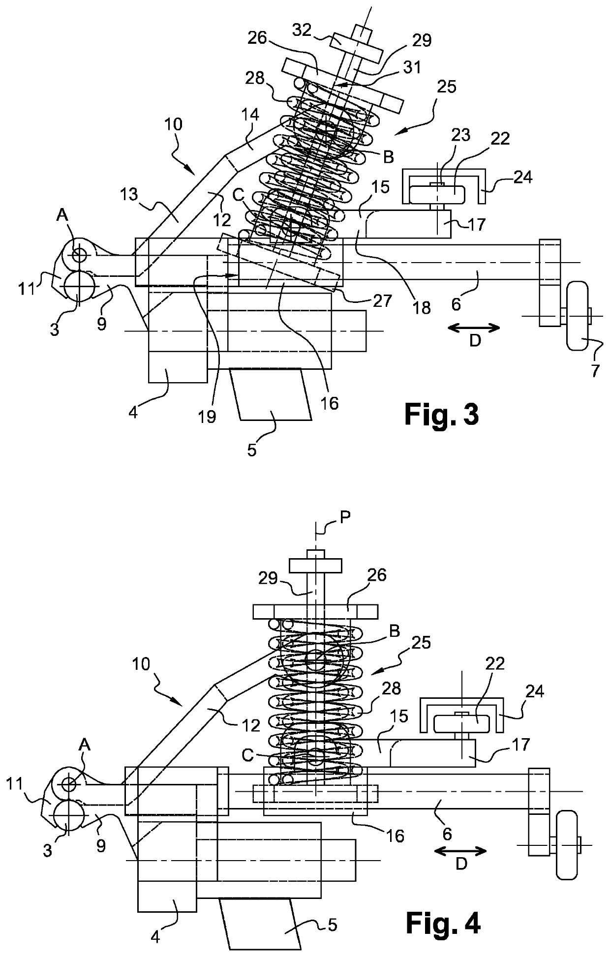
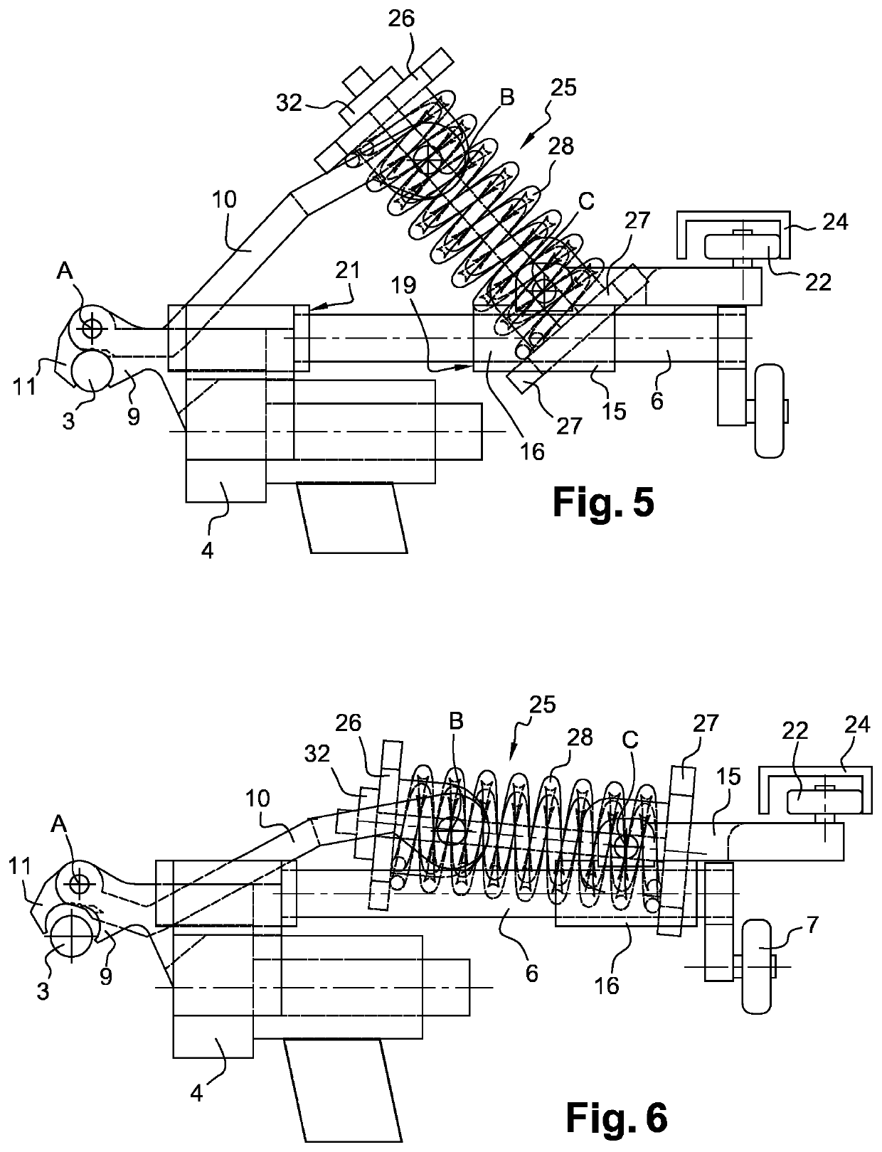
[0060]FIGS. 1 to 6 show a declutchable coupling device 2, also called declutchable coupling clip, intended to couple a vehicle, for example a cable car or a chairlift, to a traction cable 3 of an air transport installation by a traction cable. Such a coupling of the vehicle to the traction cable 3, via the coupling device 2, allows displacing the vehicle between two end stations of the transport installation. According to an embodiment of the invention, the traction cable 3 may be a hauling-traction cable.

[0061]The coupling device 2 comprises a support body 4 intended to extend transversely to the traction cable 3, and more particularly substantially perpendicularly to the traction cable 3, when the coupling device 2 is coupled to the traction cable 3. The support body 4 is intended to be connected to a hanger 5 supporting a vehicle (not shown in the figures), such as a cable car or chairlift, for example.

[0062]The support body 4 includes at least one cylindrical guide portion 6 who...


PUM


Abstract

This coupling device comprises a support body, a first clamping jaw, a clamping member comprising a second clamping jaw and a connecting portion, the clamping member being hingedly mounted on the support body between a clamping position in which the first and second clamping jaws are configured to clamp a traction cable; a biasing device configured to bias the clamping member towards the clamping position, and an actuation member configured to actuate a displacement of the clamping member between its clamping and release positions, the actuation member being slidably mounted on the support body between a first stable position in which the clamping member is in the clamping position, and a second stable position in which the clamping member is in the release position.

Description

CROSS REFERENCE TO RELATED APPLICATIONS[0001]This application is a National Stage of PCT Application No. PCT / FR2016 / 051483 filed on Jun. 17, 2016, which claims priority to French Patent Application No. 15 / 56115 filed on Jun. 30, 2015, the contents each of which are incorporated herein by reference thereto.TECHNICAL FIELD[0002]The present invention concerns a coupling device intended to couple a vehicle, for example a cable car or a chairlift, to a traction cable of a transport installation.BACKGROUND[0003]The document U.S. Pat. No. 5,111,751 describes such a coupling device which comprises in particular:[0004]a support body,[0005]a first clamping jaw fixedly mounted relative to the support body,[0006]a clamping member comprising a second clamping jaw and a connecting arm including a first end portion secured to the second clamping jaw and a second end portion opposite to the second clamping jaw, the clamping member being hingedly mounted on the support body about a first hinge axis ...

Claims


Application Information

Patent Timeline
Patent Type & Authority Patents(United States)
IPC IPC(8): B61B12/12F16F1/12
CPCF16F1/128B61B12/122
Inventor MANFREDI, RÉMIBIBOLLET-RUCHE, LUDOVIC
Owner LST
Why Eureka
Try Eureka