
High-strength fibre rope for hoisting equipment such as cranes

a high-strength, fibre-based technology, applied in the direction of textile cables, transportation and packaging, textiles and paper, etc., can solve the problems of onset of a replacement state of wear, inability to measure the replacement state of wear of high-strength fibre ropes, and no longer provided safety during further operation. achieve the effect of reliable and precise determination

Active Publication Date: 2020-10-20
TEUFELBERGER FIBER ROPE
View PDF45 Cites 0 Cited by
  • Summary
  • Abstract
  • Description
  • Claims
  • Application Information

AI Technical Summary

Benefits of technology

The present invention aims to provide a better crane rope that overcomes the shortcomings of previous designs. It should allow for a simple yet reliable and accurate determination of when the rope needs replacing, without compromising its safety.

Problems solved by technology

Like steel ropes, high-strength fibre ropes are wear parts which have to be replaced when their condition has deteriorated to such an extent that the required safety is no longer provided during further operation.
However, one difficulty associated with such high-strength fibre ropes consists in a precise and reliable prediction of the replacement state of wear.
However, said measuring method is not feasible for detecting the replacement state of wear in high-strength fibre ropes, as the employed synthetic fibres do not exhibit the same behaviour as steel wire strands.
In particular in high-strength fibre ropes, a sudden failure or, respectively, an onset of a replacement state of wear without any pre-existing damage that might be recognized gradually, often occurs, since, unlike in steel ropes, frequently individual fibres do not break and fan out gradually, but several fibre strands often fail simultaneously.
However, in practice, this colour indicator function, which, per se, is reasonable, suffers from the fact that, due to the characteristics of high-strength synthetic fibres, the sheathing tends to fail altogether rather suddenly so that it is again difficult to be able to predetermine the replacement state of wear of the rope reliably and in due time.
This approach is disadvantageous as it requires additional conductivity measurements and, associated therewith, the necessary technical infrastructure such as power source, conductivity meter, connection points for the indicator fibre.
However, the detection of a replacement state of wear caused by abrasion, in particular in rope drives in which the rope is bent over sheaves, remains unaffected thereby.

Method used


Image

  • High-strength fibre rope for hoisting equipment such as cranes
  • High-strength fibre rope for hoisting equipment such as cranes
  • High-strength fibre rope for hoisting equipment such as cranes

Examples


Embodiment Construction

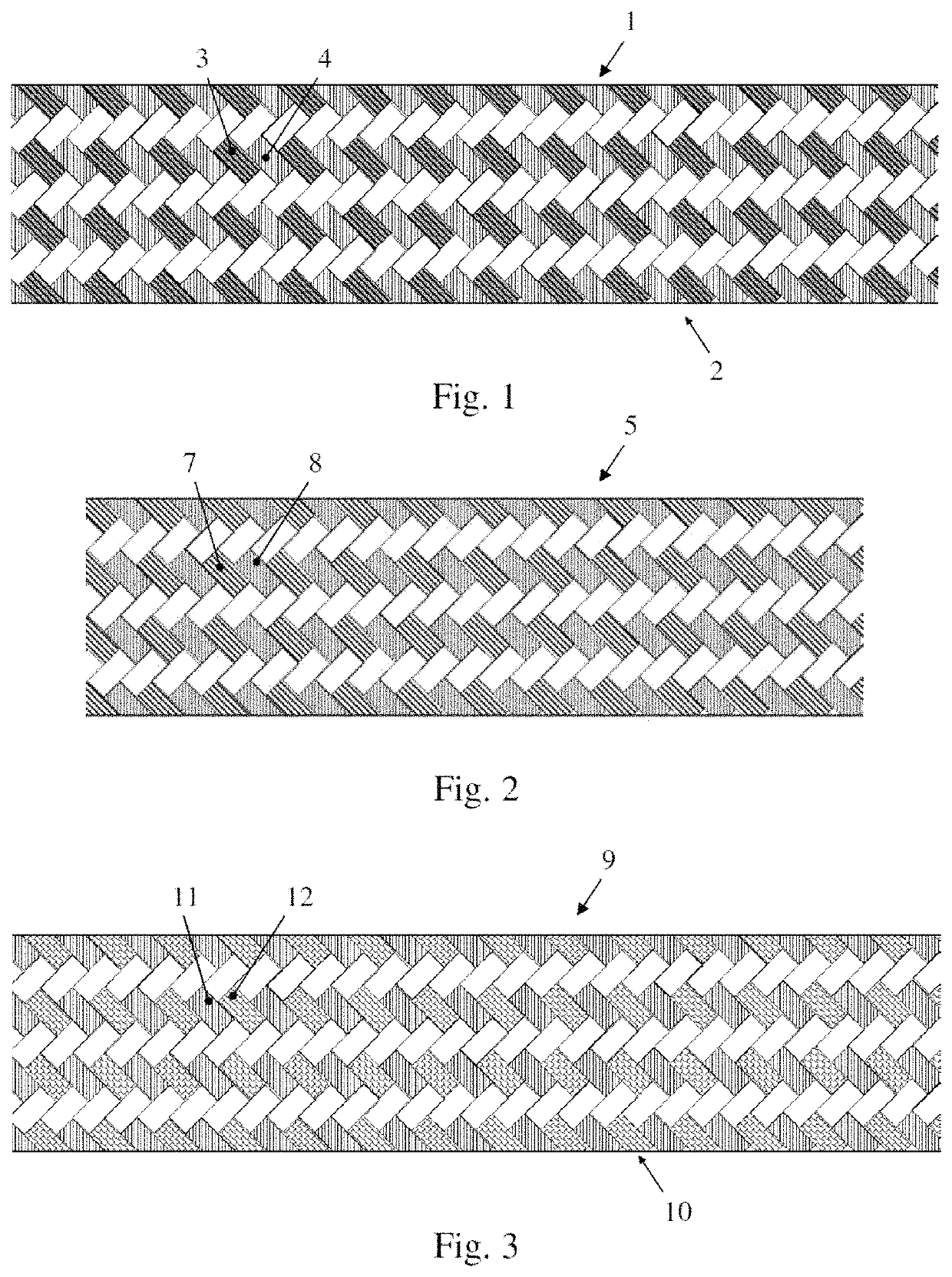
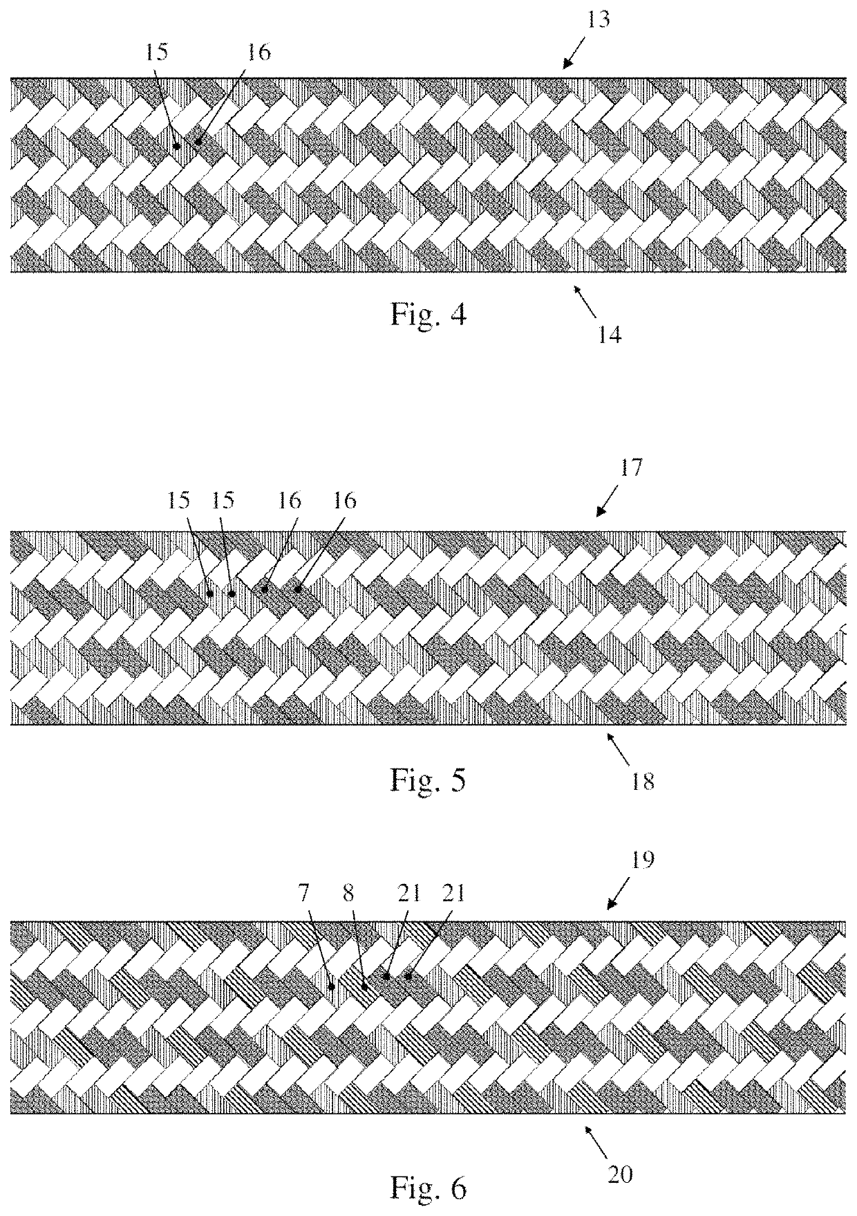
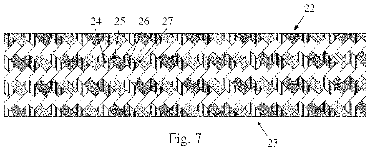
[0069]FIGS. 1 to 7 each show a detail of a design variant of a high-strength fibre rope according to the invention. Each of the high-strength fibre ropes is formed from a rope core, which is not visible in FIGS. 1 to 7, and a sheathing surrounding the rope core, wherein the sheathing is formed directly around said rope core or, optionally, can be spaced apart therefrom by an interlayer. The rope core can assume the entire indicated tensile strength of the fibre rope. In particular, said sheathing may form the outer sheath of the fibre rope and acts especially only as a support and as a protection for the rope core. The sheathing comprises an outermost sheath layer which is formed from braided 1TUEs, whereby a rhombus-shaped braiding pattern is formed. The 1TUEs and / or, if provided, the 2TUEs differ from each other in their textile structures, resulting in wear resistances of the subunits which are different in each case, from which the state of wear of the rope can be detected optic...


PUM

PropertyMeasurementUnit
strengthaaaaaaaaaa
wear resistancesaaaaaaaaaa
braid angleaaaaaaaaaa

Abstract

A high-strength fibre rope (1) comprising a rope core as well as a sheathing indicating optical wear, wherein the sheathing comprises a sheath layer (2) made up of textile subunits (3, 4) of a first hierarchy level. An outermost sheath layer (2) is provided, wherein textile subunits (3, 4) of said outermost sheath layer of the first hierarchy level differ from each other in terms of their textile structure, and / or an outermost sheath layer and a further sheath layer underneath said outermost sheath layer are provided, and wherein the textile subunits of the first hierarchy level of said outermost sheath layer differ in their textile structure from that of said further sheath layer. The textile subunits of a lowermost hierarchy level of the rope are neither dispersed in a resin matrix in the outermost sheath layer nor in the further sheath layer arranged underneath the outermost sheath layer.

Description

BACKGROUND[0001]The present invention relates to a high-strength fibre rope for hoisting equipment such as cranes, comprising a rope core comprising high-strength synthetic fibres as well as a sheathing surrounding the rope core and indicating optical wear.[0002]For quite some time, attempts have been made in hoisting technology and in particular with cranes to replace the conventional heavy steel ropes with high-strength fibre ropes which are made of high-strength synthetic fibres such as, e.g., aramid fibres (HMPA), aramid / carbon fibre mixtures, high modulus polyethylene fibres (HMPE), or poly(p-phenylene-2,6-benzobisoxazole) fibres (PBO) or at least comprise such fibres. Due to the weight reduction in comparison to steel ropes of up to 80%, with the breaking strength being approximately the same with a comparable diameter, the load capacity or, respectively, the permissible lifting capacity can be increased, since the dead weight of the rope to be taken into account for the load ...

Claims


Application Information

Patent Timeline
Patent Type & Authority Patents(United States)
IPC IPC(8): D07B1/14B66C15/00D07B1/02
CPCD07B1/145B66C15/00D07B1/02D07B1/148D07B2201/2092D07B2401/2075D07B2501/2015D07B2205/2039D07B2205/201D07B2201/104D07B2201/102D07B2205/2046D07B2205/205D07B2201/1096D07B2201/2088D07B1/025D07B2205/2096D07B2201/2066D07B2205/2014D07B2201/209D07B2201/2009D07B2801/22D07B2801/10D07B1/24D07B2201/1014D07B1/04B66C1/12
Inventor BALDINGER, PETERTRAXL, ROBERTKAISER, GUNTERKIRTH, RUDOLFERNST, BJÖRNRÜHRNÖSSL, ERICH
Owner TEUFELBERGER FIBER ROPE
Learn More