
Method for measuring the thickness of flat workpieces

a technology for workpieces and workpieces, applied in the direction of testing/measurement of semiconductor/solid-state devices, lapping machines, instruments, etc., can solve the problems of high demands on the flatness of workpieces, inability to meet the accuracy requirements explained above, and insufficient edge geometry for the requirements of wafer consumers, etc., to achieve reliable and precise in-situ determination of workpieces, reduce scrap volume, and simplify production logistics

Inactive Publication Date: 2018-03-01
PETER WOLTERS GMBH
View PDF10 Cites 3 Cited by
  • Summary
  • Abstract
  • Description
  • Claims
  • Application Information

AI Technical Summary

Benefits of technology

The invention provides a method for accurately measuring the thickness of a workpiece during processing, without the need for an external measuring instrument. The method uses a through-hole in the thickness measurement apparatus to seal the workpiece from dirt and moisture, and the thickness is determined by measuring the optical path from the light source to the workpiece. This allows for precise detection in real-time processing, without the need for a separate pre-processing step. The method can be used with different workpiece materials and can be adjusted based on the workpiece properties, such as doping concentration or temperature. The measured thickness can be used to terminate the processing operation or transfer to the next processing operation. The data evaluation can be performed with statistical or general mathematical methods, and the results can be adjusted based on calibration and corrections. Overall, the invention simplifies the process control and reduces the need for external measuring instruments.

Problems solved by technology

If the target measure is passed, for example because the processing operation takes too long, the edge geometry is generally not sufficient for the requirements of wafer consumers.
In particular, high demands are placed on the flatness of the workpieces.
However, the accuracy requirements explained above cannot always be achieved.
The accuracy requirements mentioned above cannot, however, be regularly achieved with this method either.
In particular, the external parameters change during processing, for example, due to wear.
This results in deviations from the predicted workpiece thickness.
This is complex, both from a metrological and process technology point of view.
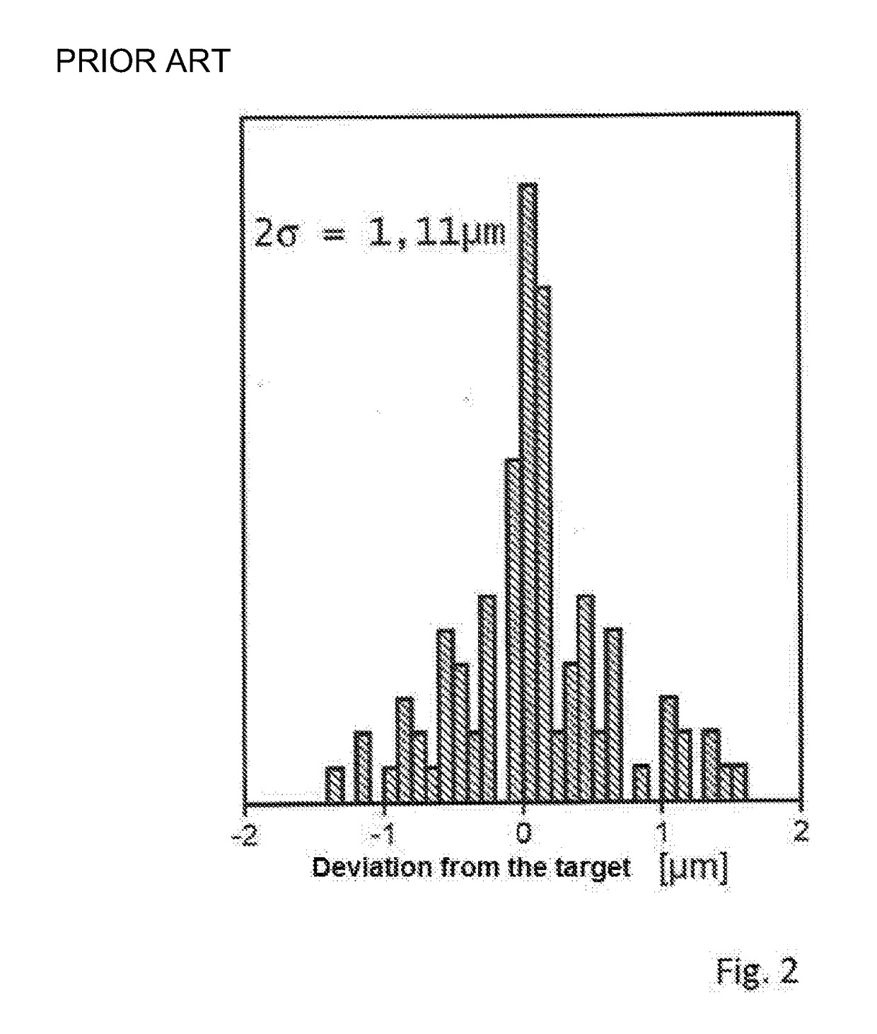
The process parameters of the processing machine are corrected at correspondingly staggered intervals, resulting in scrap.
This is complex in design and process engineering terms, and only relatively few measuring points are available.
This, in turn, adversely affects the reliability and accuracy of the measurement.

Method used


Image

  • Method for measuring the thickness of flat workpieces
  • Method for measuring the thickness of flat workpieces
  • Method for measuring the thickness of flat workpieces

Examples


Embodiment Construction

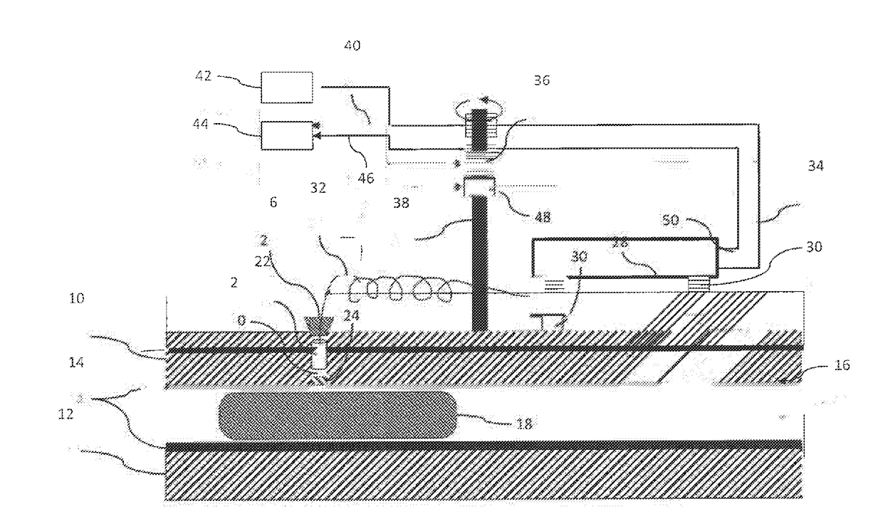
[0037]The double-side processing machine shown in FIG. 1 can, for example, be a double-side polishing machine. The double-side processing machine has an upper working disk 10 and a lower working disk 12 opposite the upper working disk 10. Part of the upper working disk 10 and the lower working disk 12 can, in each case, be a working coating 14, for example a polishing cloth. With this working coating 14, the upper and lower working disks 10, 12 delimit between them a working gap 16 for material-removing processing of workpieces. The reference numeral 18 shows, by way of example for illustrative purposes, a workpiece, for example a wafer. It is understood that, for example, rotatably arranged rotor disks can in practice be provided in the working gap 16, which rotor disks each receive multiple workpieces for simultaneous processing in the working gap 16.

[0038]In the example shown a through-hole 20, in particular a through-bore, is configured in the upper working disk 10. A focusing o...


PUM


Abstract

A method for measuring the thickness of flat workpieces processed in a double-side processing machine comprises processing the workpieces in a working gap formed between an upper working disk and a lower working disk configured to remove material from the workpieces. Optically measuring the thickness of the workpieces during processing by at least one optical thickness measurement apparatus disposed on at least one of the upper working disk or the lower working disk. The at least one optical thickness measurement apparatus configured to measure the thickness of the workpieces disposed in the working gap through at least one through-hole in a corresponding upper working disk or the lower working disk. Supplying the measurement results of the at least one thickness measurement apparatus to a control apparatus of the double-side processing machine. Terminating the processing of the workpieces once a previously specified target thickness of the workpieces is reached.

Description

CROSS REFERENCE TO RELATED INVENTION[0001]This application is based upon and claims priority to, under relevant sections of 35 U.S.C. §119, German Patent Application No. 10 2016 116 012.1, filed Aug. 29, 2016, the entire contents of which are hereby incorporated by reference.BACKGROUND[0002]The invention relates to a method for measuring the thickness of flat workpieces processed in a double-side processing machine. Flat workpieces such as wafers, in particular silicon wafers, are processed in double-side processing machines, for example double-side polishing machines to remove material from both sides of the flat workpiece. During this removal polishing of the workpieces, it is of vital importance to inspect the workpiece thickness in order to attain the quality requirements. The target window for achieving the best possible workpiece geometry is approximately 100 nm. If the target measure is passed, for example because the processing operation takes too long, the edge geometry is ...

Claims


Application Information

Patent Timeline
Patent Type & Authority Applications(United States)
IPC IPC(8): B24B37/013
CPCB24B37/013B24B49/04B24B49/12G01B11/06H01L21/304H01L22/26B24B49/045B24B37/08B24B37/205H01L22/12
Inventor KANZOW, JORNWERTH, SASCHA
Owner PETER WOLTERS GMBH
Learn More