

Oil spill clean-up and recovery systems for marine vessels
- Summary
- Abstract
- Description
- Claims
- Application Information
AI Technical Summary
Benefits of technology
Problems solved by technology
Method used
Image

Examples
first embodiment
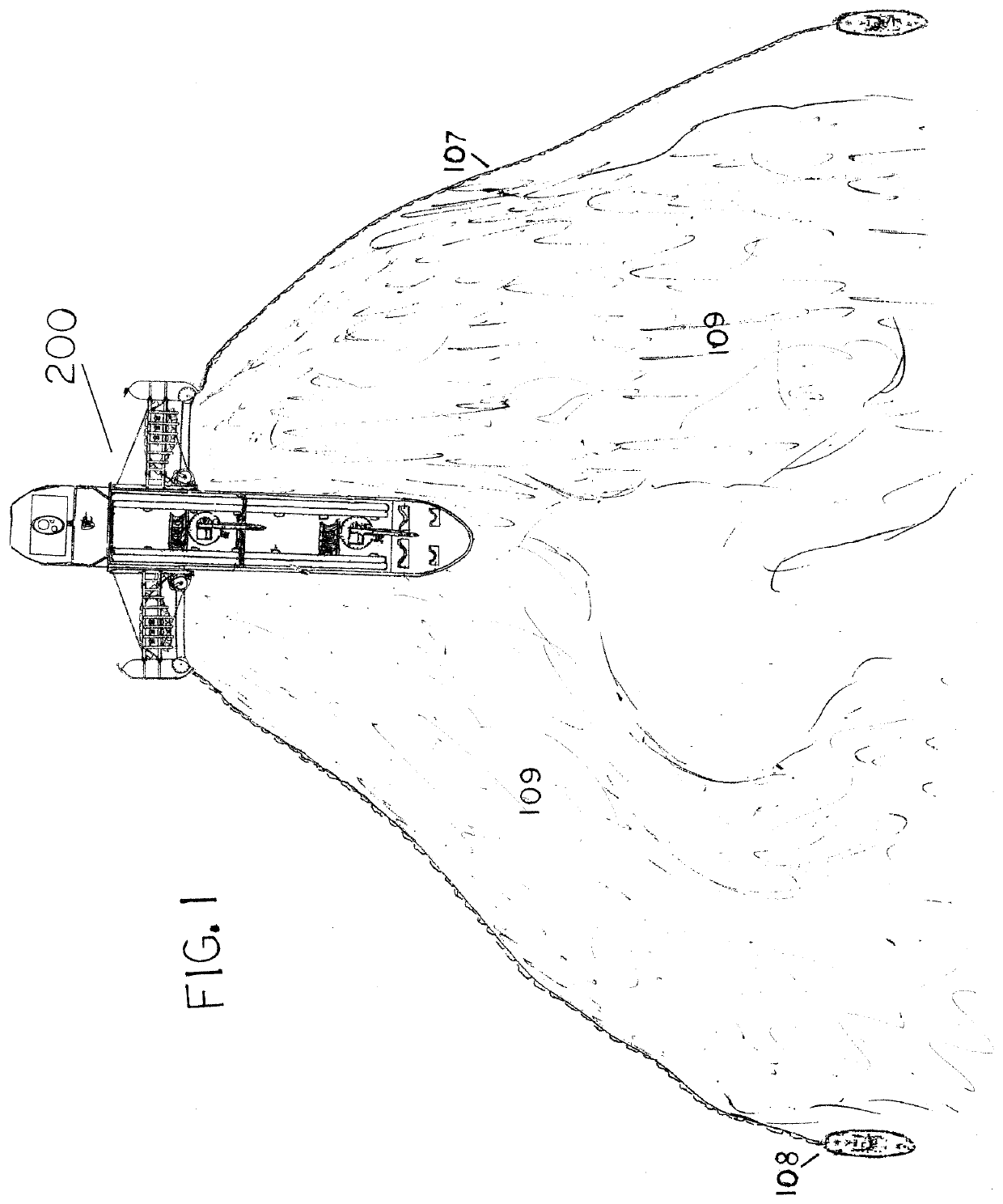
[0106]Turning now to the drawings, FIG. 1 illustrates an overhead view of the invention in a first embodiment oil cleanup vessel 200, which in most cases would be the larger of the three vessel applications of this invention that are illustrated herein. Shown is an oil clean up and recovery unit mounted on each side of the recovery vessel. The recovery vessel would be of the same approximate size as an island tanker and equipped with two oil containment boom tow boats 108, which travel ahead and outwardly to each side of the recovery vessel, and towing oil containment booms 107 that channel and corral the floating oil 109. This is accomplished by means of forward movement of the three vessels, wherein floating oil gathers and concentrates in the aft portion of the oil clean up and recovery units and the oil is pulled into intake tubes attached to floats, lead booms, and custom platform and recovery booms. They include depth level adjustment mechanisms that maintain the oil intake tu...
second embodiment
[0121]FIGS. 10A, 10B, 11A, 11B, 12A and 12B, and components referenced therein, are referenced here together and common components variously described below, and illustrate the internal works of housings for the telescopic tubes that are attached to floats. These tubes initially recover oil and a percentage of water during recovery process, which flow down to the recovery tank, and from there to the oil and water separation process. Water is pumped back over board and recovered oil is pumped into storage tanks. Tubes are illustrated as viewed through tube housing 4, depicting additional progressively smaller tubes 5 are nested one inside the other within housing 4. Housing 4 has a pivotal base 26 as seen in FIGS. 11B, and 12A. The base is employed in the first and second embodiment of this device that work in conjunction with a compression post and pitman arms 81 (shown in FIG. 25L) that maintain the tube housings vertically parallel to the vessels hull at all times.
[0122]FIGS. 10A ...
third embodiment
[0161]The pivotable pipe joints are used in an alternative embodiment, but in a completely different manner in that the telescopic tube housings 4, have no need to, and do not pivot at the base, in that the framework in this third embodiment of this invention is engineered in a way that tube housing 4 would remain vertical to the vessels transom at all times and in all seas, but the joints are actually used at least four times in this embodiment of the invention. One joint in perfect alignment with each pivot joints of the framework section located between the section of framework that attaches to the transom and houses the receiver tank, and the portion of the framework that houses the main, and the rest of this embodiment of the invention. The first two pivoting joints, being in the line that carries the oil and water solution between the float 2, and either tank 139 shown in FIG. 4, or the pump that pumps this solution into the separating tank located inside the vessel's hull. Th...
PUM
 Abstract
Description
Claims
Application Information