
Air conditioning system

a technology of air conditioning system and air intake, which is applied in ventilation systems, lighting and heating apparatuses, heating types, etc., to achieve the effects of low heat exchange energy, waste of energy consumption, and high heat exchange energy

Active Publication Date: 2020-10-20
KIMURA KOHKI CO LTD
View PDF12 Cites 0 Cited by
  • Summary
  • Abstract
  • Description
  • Claims
  • Application Information

AI Technical Summary

Benefits of technology

The patent text describes a configuration for an air conditioner system that improves cooling performance and saves energy compared to traditional methods. It uses a heat exchange medium to vaporize cooling while preventing the air conditioner from exchanging heat with the medium. The system can automatically switch between cooling and heating modes based on the space's needs, and adjusts the air volume to control the temperature and humidity. It also adjusts the heat exchange energy based on the air-conditioning load to efficiently and quickly adjust the space's air condition. This results in improved convenience and efficient air conditioning while keeping energy saving performance.

Problems solved by technology

However, even in these periods, there are cases where the air conditioner needs to perform cooling operation for the reason that the temperature of the space to be air conditioned is higher than a preset temperature of the space to be air conditioned due to solar radiation and / or the use of equipment that radiates a large amount of heat in the space to be air conditioned.

Method used


Image

  • Air conditioning system
  • Air conditioning system
  • Air conditioning system

Examples


embodiment 1

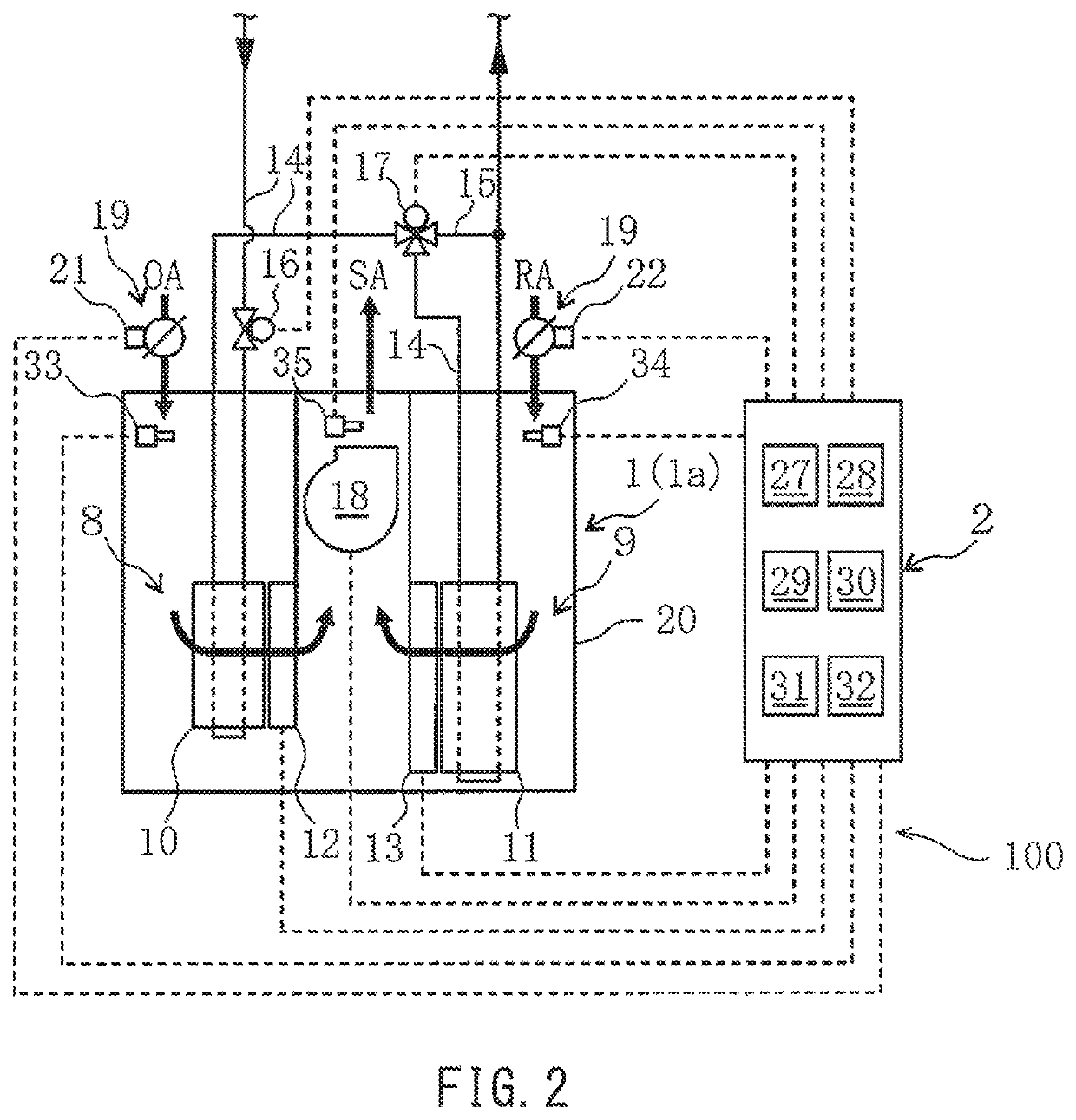
[0028]FIG. 2 shows the internal configuration of the air conditioner 1. The air conditioner 1 includes: an outside air passage 8, through which outside air serving as air-conditioning air flows; and a return air passage 9, through which return air serving as air-conditioning air flows. The air conditioner 1 includes the following components in its casing 20: an outside air heat exchanger 10, at which the outside air serving as air-conditioning air exchanges heat with the heat exchange medium; a return air heat exchanger 11, at which the return air serving as air-conditioning air exchanges heat with the heat exchange medium; an outside air vaporizing humidifier 12 configured to humidify the outside air of the outside air passage 8 by utilizing evaporation of water; a return air vaporizing humidifier 13 configured to humidify the return air of the return air passage 9 by utilizing evaporation of water; and an air blower 18. Each humidifier 12 or 13 performs the humidification when pow...

embodiment 2

[0046]FIG. 5 shows a configuration that is a result of eliminating the outside air vaporizing humidifier 12 from the air conditioner 1 shown in FIG. 2, and instead, incorporating a steam humidifier 40 into the air conditioner 1 shown in FIG. 2. The steam humidifier 40 is configured to humidify, between the air-conditioning air of the outside air passage 8 and the air-conditioning air of the return air passage 9, at least the air-conditioning air (outside air) of the outside air passage 8 by utilizing steam. In addition, the air conditioner control device 2 includes, instead of the first vaporizing cooler 31, the following components: a humidifying heater 41 configured to operate the steam humidifier 40 to heat the air-conditioning air while preventing the air-conditioning air from exchanging heat with the heat exchange medium; and a second vaporizing cooler 42 configured to operate the return air vaporizing humidifier 13 to perform vaporization cooling of the return air while preven...

embodiment 3

[0051]FIG. 6 shows a configuration that is a result of eliminating the outside air damper 21, the return air damper 22, and the air blower 18 from the embodiment shown in FIG. 2, and instead, incorporating an outside-air blower 45 provided on the outside air passage 8 and a return-air blower 46 provided on the return air passage 9 into the embodiment shown in FIG. 2. The outside-air blower 45 and the return-air blower 46 serve as the air volume adjusting device 19. The outside-air blower 45 and the return-air blower 46 are capable of adjusting the air volume of the outside air of the outside air passage 8 and the air volume of the return air of the return air passage 9 through the control of increasing / decreasing the rotational speed of each of the blowers 45 and 46. Since the other configuration features and operation examples of Embodiment 3 are the same as those of the embodiment shown in FIG. 2, the description thereof is omitted.


PUM


Abstract

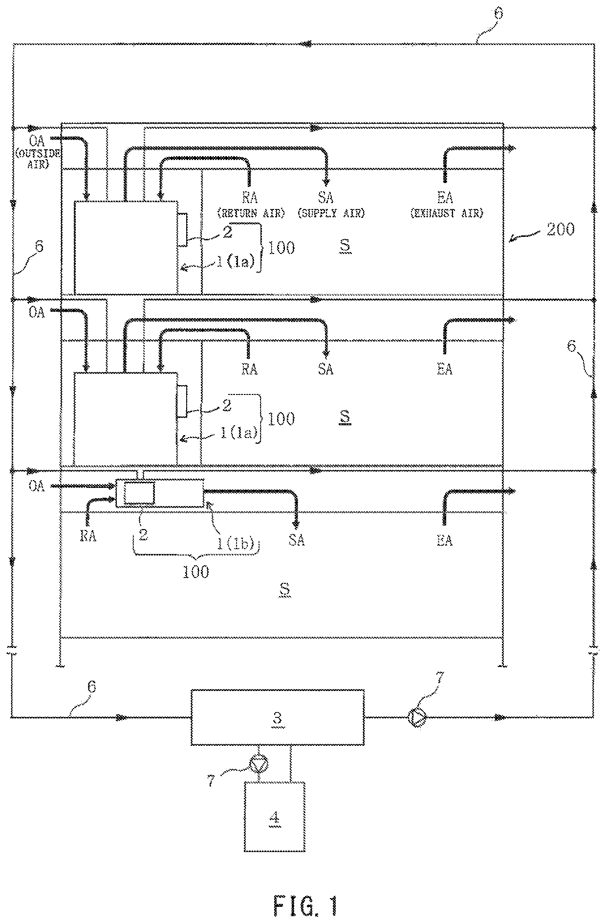
An air conditioning system includes: an air conditioner configured to supply air-conditioning air; and an air conditioner control device configured to control the air conditioner. The air conditioner includes: an outside air passage, through which outside air flows; a return air passage, through which return air flows; an outside air heat exchanger; a return air heat exchanger; an outside air vaporizing humidifier configured to humidity the outside air by utilizing evaporation of water; and a return air vaporizing humidifier configured to humidify the return air by utilizing evaporation of water. The air conditioner control device includes a first vaporizing cooler configured to operate at least one of the humidifiers to perform vaporization cooling of the air-conditioning air while preventing the air-conditioning air from exchanging heat with a heat exchange medium.

Description

CROSS-REFERENCE TO RELATED APPLICATION[0001]This application claims priority to and the benefit of Japanese Patent Application No. 2018-16360, filed on Feb. 1, 2018, and Japanese Patent Application No. 2018-78815, filed on Apr. 17, 2018, the entire disclosure of which are incorporated herein by reference.BACKGROUND OF THE INVENTIONField of the Invention[0002]The present invention relates to an air conditioning system.Description of the Related Art[0003]In air conditioning system industries, generally speaking, a one-year period is divided into a “summer period”, a “winter period”, and “intermediate periods”. Spring and autumn periods are the “intermediate periods”. In these intermediate periods, heating and cooling are used less frequently. One of conventional air conditioning systems is disclosed in, for example, Japanese Laid-Open Patent Application Publication No. 2009-162411. The conventional air conditioning system includes two heat exchangers, and causes outside air and return...

Claims


Application Information

Patent Timeline
Patent Type & Authority Patents(United States)
IPC IPC(8): F24F11/30F24F1/0087F24F6/18F24F1/0035F24F3/00F24F6/12F24F6/02F24F3/14F24F11/72F25B49/02F24F5/00F25B13/00F24F110/12
CPCF24F3/14F24F6/18F24F11/30F24F6/02F24F1/0087F24F1/0035F24F3/001F24F11/72F25B49/022F24F2005/0025F25B13/00F24F2110/12F25B2400/06F24F7/08F24F11/74F24F13/30
Inventor KIMURA, KEIICHIMORITA, MITSUOISHIDA, TAKAYUKIGOTO, KAZUYASATO, HIDEKAZU
Owner KIMURA KOHKI CO LTD
Learn More