
Head-mounted display tracking using corner reflectors

a technology of corner reflectors and head-mounted displays, which is applied in the direction of using reradiation, instruments, sport apparatus, etc., can solve the problems of cumbersome setups, unfavorable adoption and continued and unfavorable use of hmd systems

Active Publication Date: 2020-10-27
SONY COMPUTER ENTERTAINMENT INC
View PDF6 Cites 2 Cited by
  • Summary
  • Abstract
  • Description
  • Claims
  • Application Information

AI Technical Summary

Benefits of technology

The present patent describes a device that uses corner reflectors to track a head-mounted display (HMD) in a virtual or augmented reality environment. The device emits a scanning beam that continuously traces a predefined scan pattern and detects reflections of the beam from multiple reflectors. The detected reflections are used to determine the location or orientation of the HMD in the environment. The device then generates a view of a virtual space based on the determined location or orientation of the HMD. The technical effect of this invention is to provide a more accurate and efficient means of tracking the HMD, which improves the overall quality of the virtual or augmented reality experience.

Problems solved by technology

These emitters or sensors must be connected to the central computing device by lengthy wires or cables that can be unsightly and difficult to manage.
Coupled with the fact that additional cables are typically necessary for the HMD device itself, and such setups are cumbersome in terms of placement and connection of all of the different devices.
The complexity of such setups further poses a barrier to the adoption and continued use of HMD systems.

Method used


Image

  • Head-mounted display tracking using corner reflectors
  • Head-mounted display tracking using corner reflectors
  • Head-mounted display tracking using corner reflectors

Examples


Embodiment Construction

[0051]The following implementations of the present disclosure provide devices, methods, and systems relating to tracking of a head mounted display (HMD) using corner reflectors. It will be obvious, however, to one skilled in the art, that the present disclosure may be practiced without some or all of the specific details presently described. In other instances, well known process operations have not been described in detail in order not to unnecessarily obscure the present disclosure.

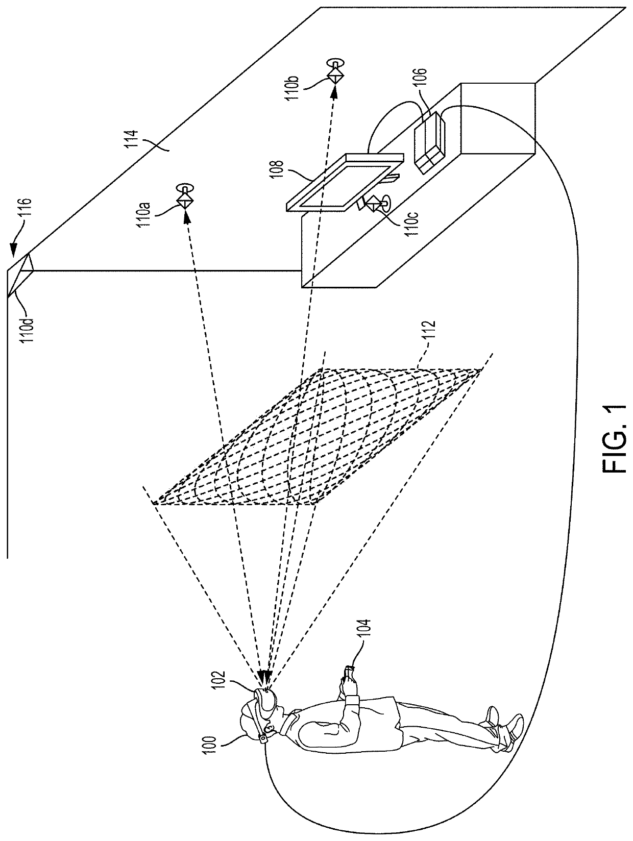
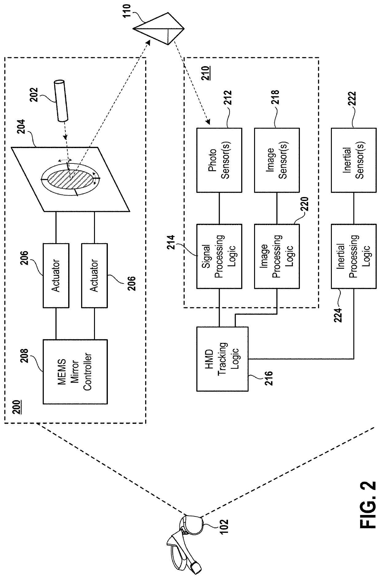
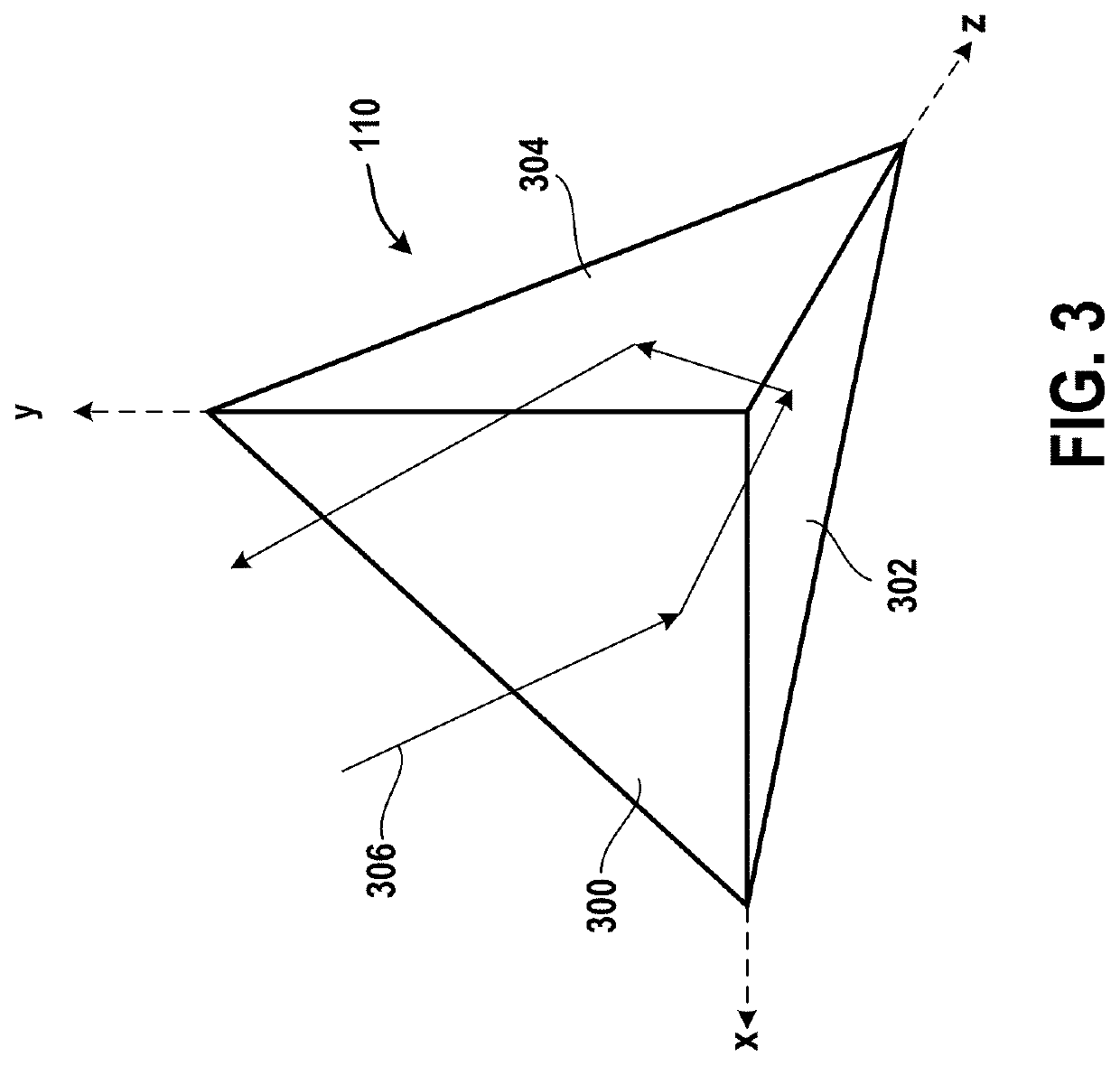
[0052]Broadly speaking, implementations of the present disclosure provide systems and methods employing a plurality of corner reflectors for tracking of an HMD in an interactive environment. The HMD is configured to have at least one emitter that emits a scanning beam that traces a predefined scan pattern. For example, the predefined scan pattern can be a raster scan pattern or a Lissajous scan pattern. The emitter hardware can include a beam generator that generates the beam and directs it towards a mi...


PUM


Abstract

A head-mounted display (HMD) is provided, including the following: an emitter configured to emit a scanning beam into an interactive environment in which the HMD is disposed, the scanning beam being configured to continuously trace a predefined scan pattern; a detector configured to detect reflections of the scanning beam back to the HMD by each of a plurality of reflectors; a processor configured to, for each reflector, determine a time at which the reflection of the scanning beam by the reflector occurred, wherein the time is used to determine a location or orientation of the HMD in the interactive environment; a display device configured to render a view of a virtual space that is determined based on the determined location or orientation of the HMD.

Description

CLAIM OF PRIORITY[0001]This application claims priority from U.S. Provisional Patent Application No. 62 / 519,716, filed Jun. 14, 2017, entitled “HEAD-MOUNTED DISPLAY TRACKING USING CORNER REFLECTORS,” the disclosure of which is herein incorporated by reference.BACKGROUND1. Field of the Disclosure[0002]The present disclosure relates to tracking of a head-mounted display (HMD) using corner reflectors, and related methods, apparatus, and systems.2. Description of the Related Art[0003]The video game industry has seen many changes over the years. As computing power has expanded, developers of video games have likewise created game software that takes advantage of these increases in computing power. To this end, video game developers have been coding games that incorporate sophisticated operations and mathematics to produce very detailed and engaging gaming experiences.[0004]Example gaming platforms include the Sony Playstation®, Sony Playstation2® (PS2), Sony Playstation3® (PS3), and Sony...

Claims


Application Information

Patent Timeline
Patent Type & Authority Patents(United States)
IPC IPC(8): G02B27/01G06F3/01A63F13/213A63F13/212A63F13/24A63F13/5255G01S17/66G01S17/42G02B30/50G02B26/12G02B26/08
CPCA63F13/24G01S17/42A63F13/212G02B27/017G02B30/50G02B26/0833G06F3/012G02B27/0172G02B26/127A63F13/5255G01S17/66A63F13/213G02B2027/0187G02B2027/014
Inventor MALLINSON, DOMINICZALEWSKI, GARY
Owner SONY COMPUTER ENTERTAINMENT INC
Learn More