
Foundations system for towers and method for installing the foundations system for towers

a technology for foundation systems and towers, applied in the direction of towers, buildings, constructions, etc., can solve the problems of high construction costs, high construction times, and more sensitive execution, and achieve the effect of maximizing the proportion of the total weight of the foundation, and reducing the maximum amount of materials

Active Publication Date: 2020-11-03
ESTEYCO ENERGIA
View PDF10 Cites 1 Cited by
  • Summary
  • Abstract
  • Description
  • Claims
  • Application Information

AI Technical Summary

Benefits of technology

The present invention aims to reduce the cost of foundations in construction by using less reinforced and pre-stressed concrete, while still maintaining their basic functions. This is done by maximizing the proportion of the weight of the foundation by gravity obtained from the weight of soil that gravitates on it. The construction method is easy and fast, as many elements can be prefabricated to reduce construction time and facilitate in-situ industrialization processes.

Problems solved by technology

On one hand, in the case that external loads to withstand are high, as usual, the first drawback is its high cost, since it requires a slab of large volume with high measurements of concrete and steel to provide enough weight to support the tipping stresses.
Furthermore, assuming high volumes of in-situ construction, it also requires high construction times, which in turn makes its execution more sensitive to weather conditions.
Furthermore, it is a solution which entails considerable constructive complexity, very long connections between different elements and processes that lend themselves difficult for industrialization.
However, in these solutions the struts are not elements of the foundation system, but part of the not buried structure of the tower, because they are connected at its upper end directly to the tower wall and they are essentially not buried elements; and they are high dimension elements and their handling and construction is complicated.

Method used


Image

  • Foundations system for towers and method for installing the foundations system for towers
  • Foundations system for towers and method for installing the foundations system for towers
  • Foundations system for towers and method for installing the foundations system for towers

Examples


Embodiment Construction

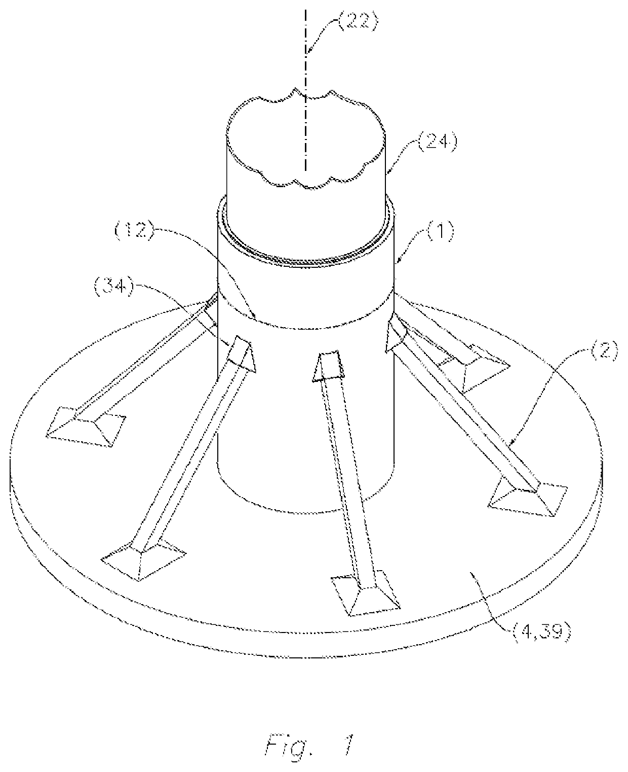
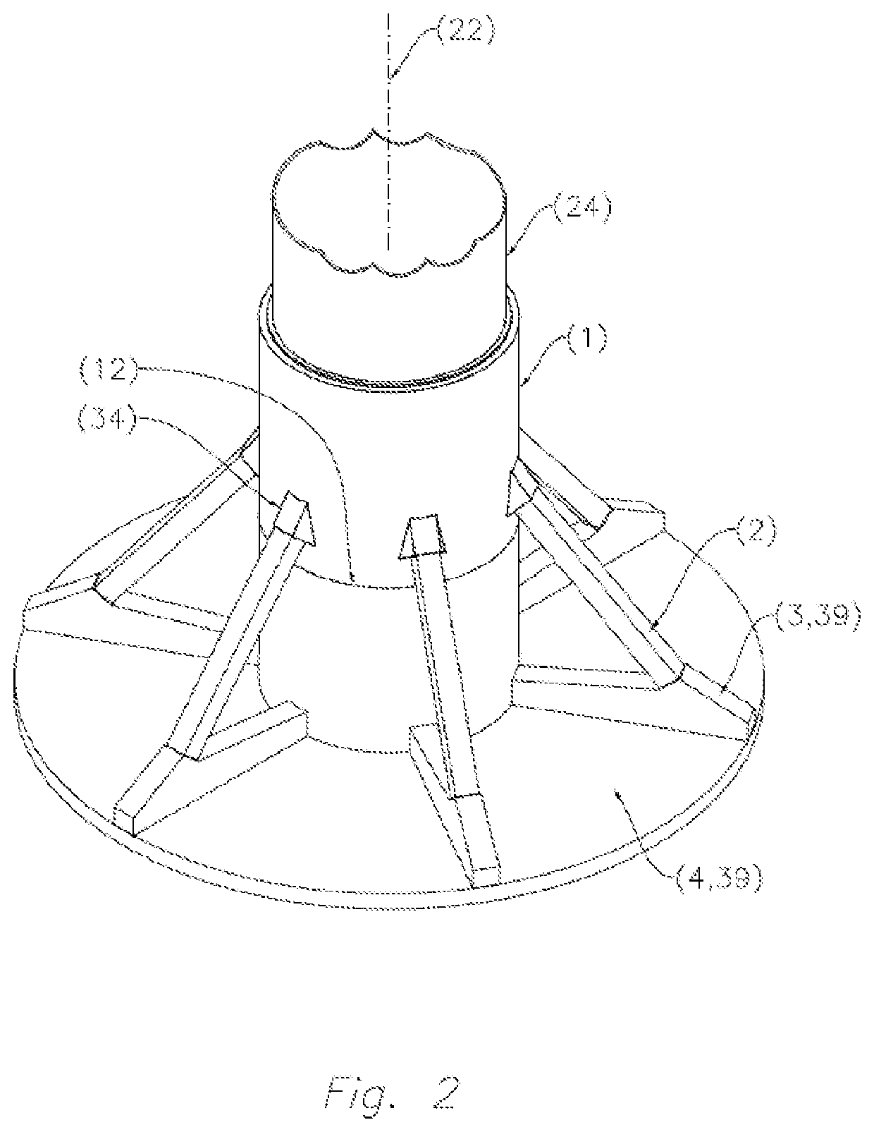
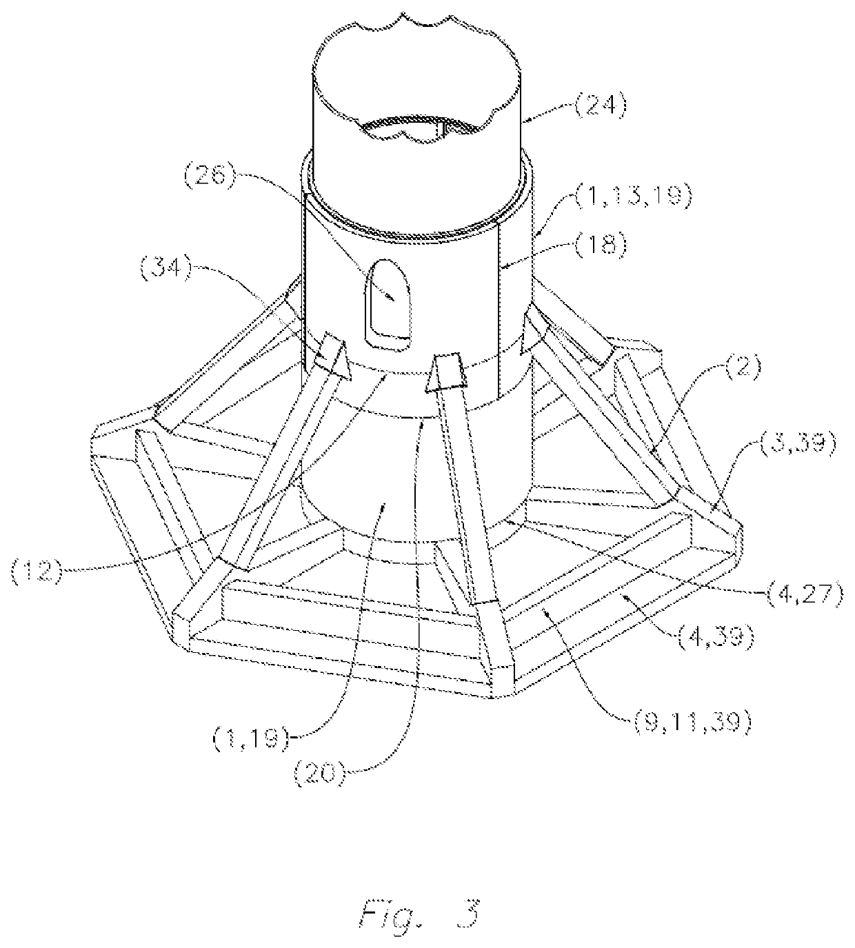
[0094]FIG. 1 shows the tower foundation system according to the invention in which it can be seen that there are the following elements: a central shaft (1) mostly buried, a lower slab (4) completely buried and lateral support means comprising, in this case six struts (2) also completely buried.

[0095]The central shaft (1) is located below the base of the tower (24) so that, preferably, its central vertical axis is essentially coincident with the vertical axis (22) of the tower (24), which in this case it is a tubular metal tower.

[0096]The central shaft (1) is cylindrical in this embodiment, but it can be of any shape, and it can be, without being an exhaustive list, circular, polygonal, cylindrical, tapered or with variable tilting of the walls. Also, this central shaft (1) can also be hollow or solid.

[0097]The lower slab (4) is located below the central shaft (1) so that, preferably, its center is essentially coincident with the vertical axis of the tower (24) and is completely bur...


PUM


Abstract

Foundation system for towers, especially for onshore wind turbines, comprising a central shaft buried or partially buried, preferably hollow and formed by dowels made from precast concrete, an essentially flat lower slab and completely buried, and lateral support means in the form of inclined struts that are joined at their upper end with the central shaft and at its lower end with the lower slab, and that are preferably entirely buried. The wind tower is located on the partly buried main shaft. The foundation system may comprise other lower elements connected with the lower slab, such as radial ribs or peripheral beams. The struts are preferably prefabricated elements incorporating an efficient and economical connection system by pre-stressing. The foundation system maximizes the fraction of the weight of the foundation by gravity generated by soil or ballast material, allowing an important economy in the structural materials of the foundation.

Description

TECHNICAL FIELD[0001]The present invention relates to a foundation system for wind towers on land or on-shore, and to a method for installing the foundation system for towers according to the invention.[0002]This foundation system for towers and the method for installing the foundation system for towers can be used to support towers or structures of high external loads and / or large dimensions. Preferably, the application scope of the system and method according to the invention is the construction industry and the field of power industry, in particular, wind energy, wherein concrete or metal towers or structures are used. Its application scope is focused on building on-shore towers.PRIOR ART[0003]Today the vast majority of wind turbines are founded on conventional shoes that work by gravity. This type of foundation consists of a slab of any plan shape (circular, polygonal, etc.) located below the ground on which the structure or tower to be supported must be placed. This slab is usu...

Claims


Application Information

Patent Timeline
Patent Type & Authority Patents(United States)
IPC IPC(8): E02D27/42E04H12/22F03D13/20
CPCE04H12/2269E02D27/42E02D27/425F03D13/22E02D2300/002E02D2600/40E02D2250/0046E02D2200/1678Y02E10/72Y02E10/728E02D2600/20E02D2200/16
Inventor SERNA GARCÍA-CONDE, JOSÉ SALUSTIANO
Owner ESTEYCO ENERGIA
Learn More