Low-pitch variable-setting fan of a turbine engine

a variable setting, low-pitch technology, applied in the direction of machines/engines, liquid fuel engines, rotors, etc., can solve the problems of difficult flight with the remaining engine, unfavorable drag of the airplane, and risk of over-speed, and achieve low axial and radial bulk, low cost, and high bypass ratio

Active Publication Date: 2020-11-10
SN DETUDE & DE CONSTR DE MOTEURS DAVIATION S N E C M A
View PDF34 Cites 0 Cited by
  • Summary
  • Abstract
  • Description
  • Claims
  • Application Information

AI Technical Summary

Benefits of technology

[0010]One objective of the invention is therefore to propose a system for a turbine engine comprising a variable-setting fan capable of avoiding having the blades enter the “flat pitch” position in the event of failure of the pitch change mechanism, for a moderate balance weight compared with the prior art, which has low axial and radial bulk and which can also be adapted to a turbine engine having a high bypass ratio.

Problems solved by technology

The blade is then found to be in a position called “flat pitch” in which the blades form an angle of approximately 0° with the plane of rotation of the blades (that is the plane comprising the pivoting axes of the blades of the rotor, which is perpendicular to the axis of rotation of the rotor), which is very unfavorable for the drag of the airplane.
In fact, in this position, the drag of the rotor is a maximum and can put the aircraft in danger by reducing the lift to drag ratio of the aircraft, which makes flight difficult to continue with the remaining engine(s) by generating excessive drag, by creating a risk of over-speed and / or by generating strong asymmetry between the drags of the turbine engines of the aircraft, in the case where only one of them has malfunctioned (which can make the airplane impossible to control).
One of the constraints of the blade setting control systems is therefore to bring these into a position called “feathered” in the case of a failure of the pitch change mechanism of the blade.
In this position, the chord of the blades is substantially aligned with the wind direction, thus reducing the drag that they generate and, consequently, the yaw imbalance produced on the aircraft.
This solution can, however, be penalizing in terms of mass, because it necessitates the use of heavy counterweights of which the effect is not geared down.
Moreover, this system weighs down the turbine engine, which increases its specific fuel consumption.
However, freedom of choice still remains limited due to the constraints connected with the bulk of this system with respect to the available space.
These constraints can therefore lead to preventing the integration of the system into the rotor (propeller or fan).

Method used


Image

  • Low-pitch variable-setting fan of a turbine engine
  • Low-pitch variable-setting fan of a turbine engine
  • Low-pitch variable-setting fan of a turbine engine

Examples


first embodiment

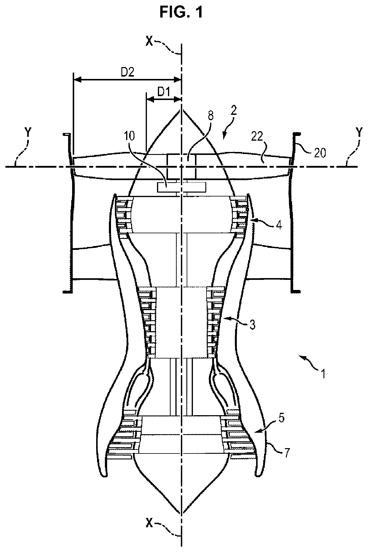
[0041]In a first embodiment, the pitch change mechanism 8 is collective. This mechanism is of the ram type and is configured to drive the fan blades in pivoting around their pivoting axes Y depending on the flight phases of the turbine engine 1. Collective pitch change mechanisms 8 are known to persons skilled in the art.

[0042]For one example of this type, it is possible [to refer] to patent application FR 1650041 which proposes a system for controlling the orientation of the blades of a turbine engine fan in which the movable portion of a ram is coupled to pivots of the fan blades so that translation of the movable portion of the ram causes a modification of the orientation of said blades and therefore of their setting.

second embodiment

[0043]In a second embodiment, the pitch change mechanism 8 can be individual.

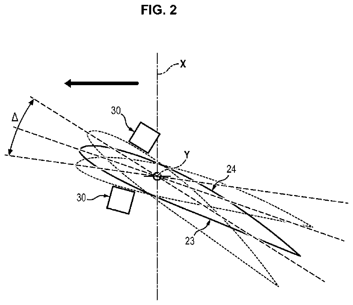
[0044]The applicants became aware that, thanks to the presence of the fan casing 20, speed variations upstream of the fan 2 are limited regardless of the flight phase. It is therefore possible to reduce the necessary range Δ of variation for the setting angle of the blades 22 of the fan 2.

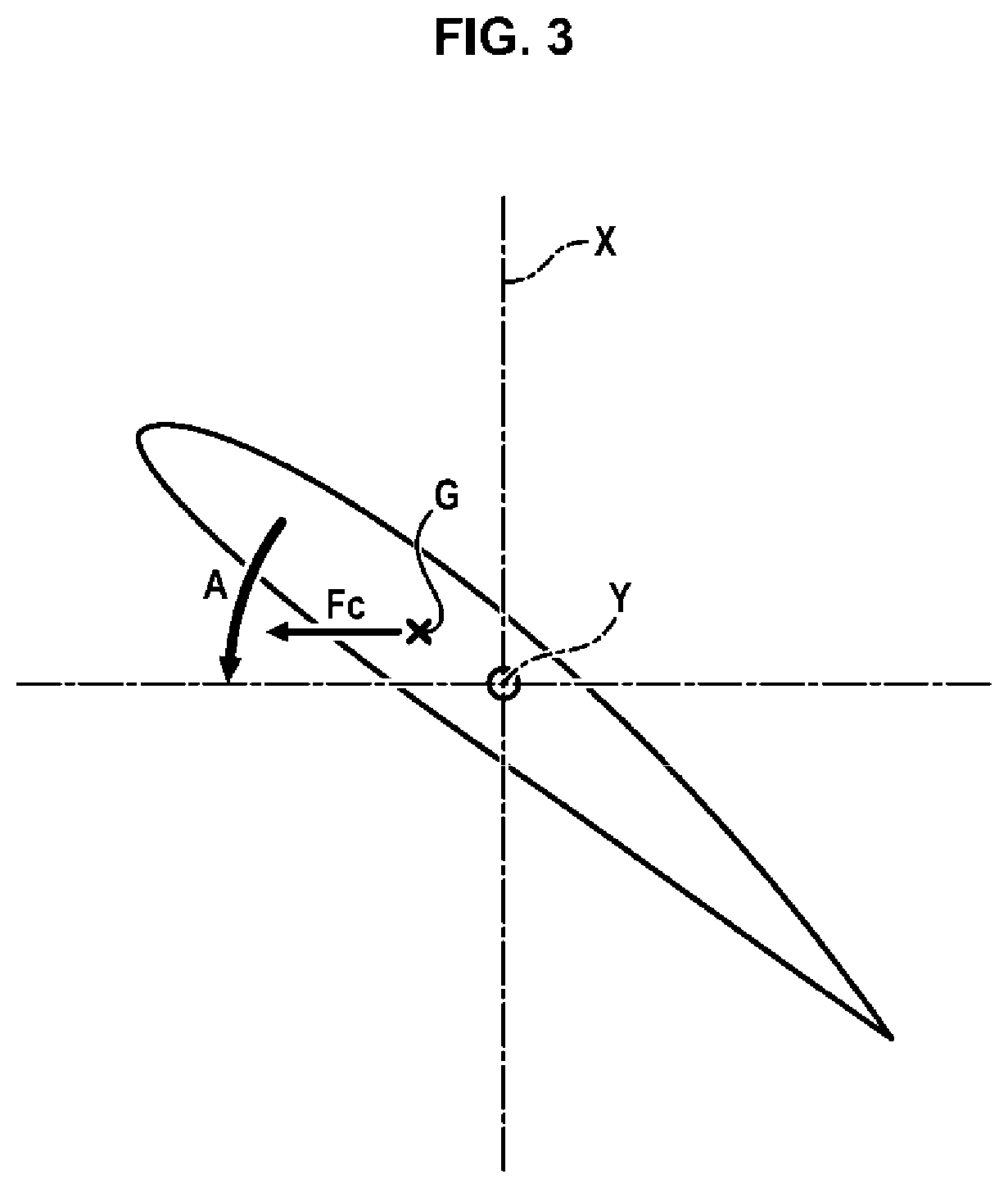
[0045]In order to avoid the blades 22 setting themselves into the flat pitch position in the event of failure of the pitch change mechanism 8, the range Δ of variation of the setting angle of the blades 22 of the fan 2 is limited to approximately 20°. Thus, whatever position is taken by the blade 22 under the influence of the centrifugal forces, it does not risk generating excess drag for the aircraft.

[0046]The range Δ of variation of setting angles of the blades 22 comprises the angular position of the blade 22 in the cruise phase.

[0047]In one embodiment, the angular setting range Δ of each blade 22 is centered on an angu...


PUM


Abstract

A fan of a turbine engine includes a disc provided with blades at the periphery thereof, the blades being mounted so as to pivot on the disc about a pivot axis, and a mechanism for changing the pitch of the blades. The mechanism is configured to adjust an angular position of each blade around the pivot axis. The angular position is in an angular setting range no greater than 20°.

Description

FIELD OF THE INVENTION[0001]The invention relates to the field of turbomachines comprising a propeller or a variable-setting fan.TECHNOLOGICAL BACKGROUND[0002]Different architectures of turbine engines have recourse to a propeller (turboprop, open rotor) or a variable-setting fan. This variability allows the turbine engine to adapt itself to flight conditions by maintaining a favorable angle of attack of the air on the blades. The variability of the setting is particularly necessary for rotors having a low pressure ratio, such as the propellers of turboprops and the fans of turbine engines having a high bypass ratio (ratio between the flow rate of the secondary (cold) flow and the flow rate of the primary flow (which passes through the primary body)).[0003]Multiple devices have been imagined to vary the setting of the blades. These devices generally include rotation of the blade around its main axis by means of conical gears, situated below the root of the blade. The latter cooperat...

Claims


Application Information

Patent Timeline
Patent Type & Authority Patents(United States)
IPC IPC(8): F01D7/00F04D29/36F02K3/06
CPCF04D29/362F01D7/00F02K3/06F05D2260/79F05D2220/36F05D2260/74F04D29/323Y02T50/60
Inventor CUVILLIER, ROMAIN GUILLAUMEBORDONI, NILS EDOUARD ROMAINBRAULT, MICHEL GILBERT ROLANDKUBIAK, GUILLAUME PATRICENEGRI, ARNAUD NICOLASNOWAKOWSKI, NATHALIEPATSOURIS, EMMANUEL PIERRE DIMITRITAJAN, SEBASTIEN EMILE PHILIPPE
Owner SN DETUDE & DE CONSTR DE MOTEURS DAVIATION S N E C M A
Why Eureka
Try Eureka