Axially segmented guide vane mount for a gas turbine

a technology of guide vane and gas turbine, which is applied in the direction of stators, machines/engines, liquid fuel engines, etc., can solve the problems of high thermal load on components and parts, correspondingly cost-intensive and technically costly construction of cast parts, etc., and achieves a simple construction of stator blade carriers and the entire gas turbine. , the effect of reducing the impact of temperatur

Inactive Publication Date: 2011-11-03
SIEMENS AG
View PDF21 Cites 24 Cited by
  • Summary
  • Abstract
  • Description
  • Claims
  • Application Information

AI Technical Summary

Benefits of technology

[0020]The advantages which are associated with the invention are especially that as a result of the design of an axial segment of a stator blade carrier as a tubular lattice structure, a technically significantly simpler, lighter and more cost-effective construction of a stator blade carrier and therefore of the entire gas turbine becomes possible. In particular, more favorable materials can be used in the regions with lower temperature impact and cost-intensive high-temperature materials stay limited to the front, hot region of the gas turbine. Furthermore, the remaining axial segments which are produced from cast parts are comparatively smaller, as a result of which a simpler construction of the stator blade carrier and of the entire gas turbine becomes possible.
[0021]Since the tubular lattice structure is poorer in heat conductivity than a solid cast part, a lower conduction of heat in the axial direction takes place, moreover, especially from the hot regions at the compressor exit to the rear, cooler regions, as a result of which improved cooling of the stator blade carrier and consequently a lower axial, and possibly also radial, thermal expansion are achieved. As a result, this construction shows great potential for stator blade carriers which are to be further developed since thermal and mechanical requirements can be met in a more flexible manner. In the front region of the turbine stator blade carrier there are exceedingly high requirements for maintaining the gaps to the stator blades and rotor blades in order to ensure the turbine efficiency. With segmenting by means of the tubular lattice construction, the thermal expansion behavior can be established to a very much better degree than previously and therefore the required minimum gap can be made smaller.

Problems solved by technology

With such high temperatures of the operating medium, however, the components and parts which are exposed to this are subjected to high thermal loads.
In any case, at least in the case of large gas turbines, however, the result is one or more very large cast part(s) which requires, or require, a correspondingly cost-intensive and technically costly construction.

Method used


Image

  • Axially segmented guide vane mount for a gas turbine
  • Axially segmented guide vane mount for a gas turbine
  • Axially segmented guide vane mount for a gas turbine

Examples


Embodiment Construction

[0025]Like parts are provided with the same designations in all the figures.

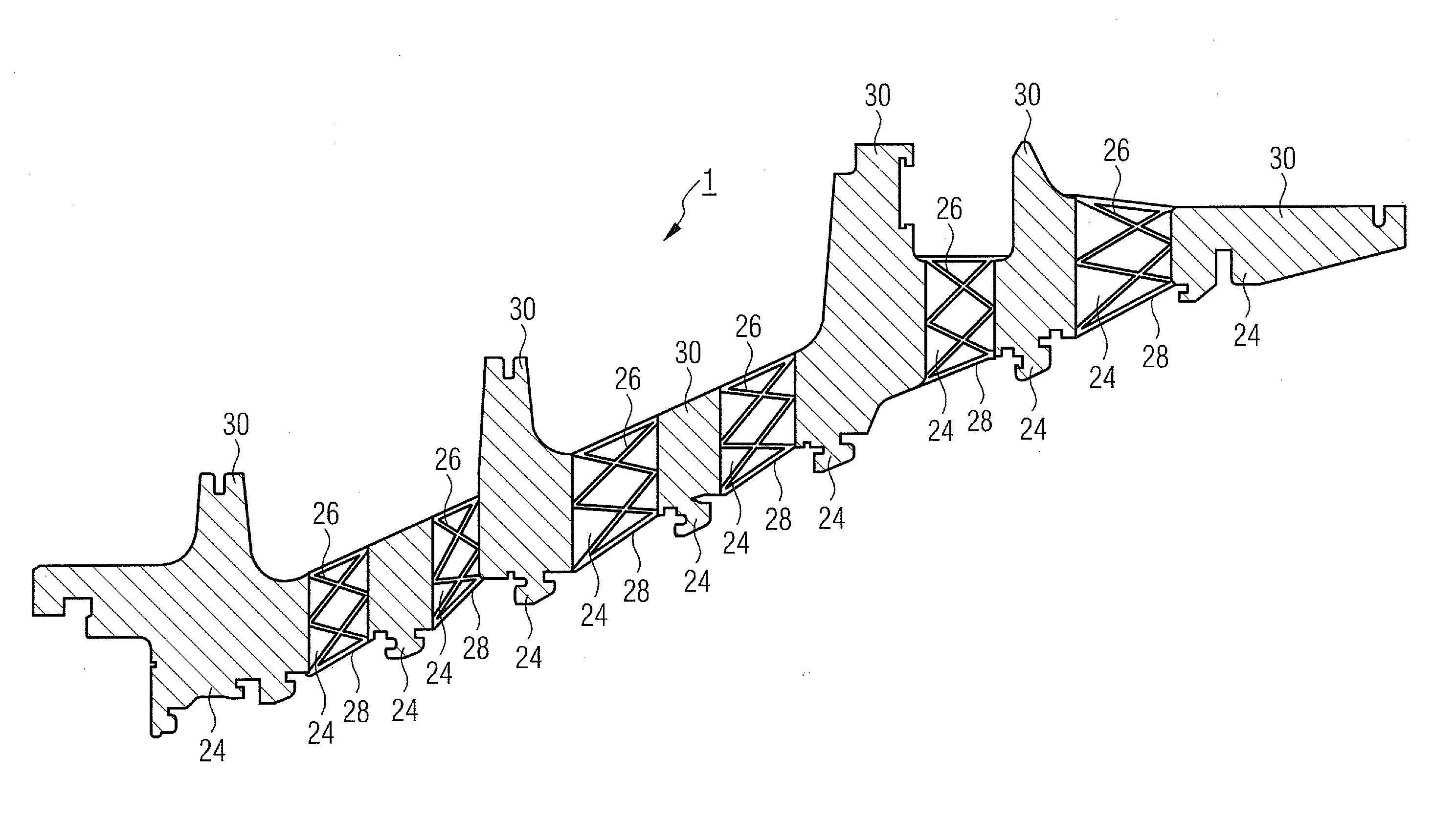
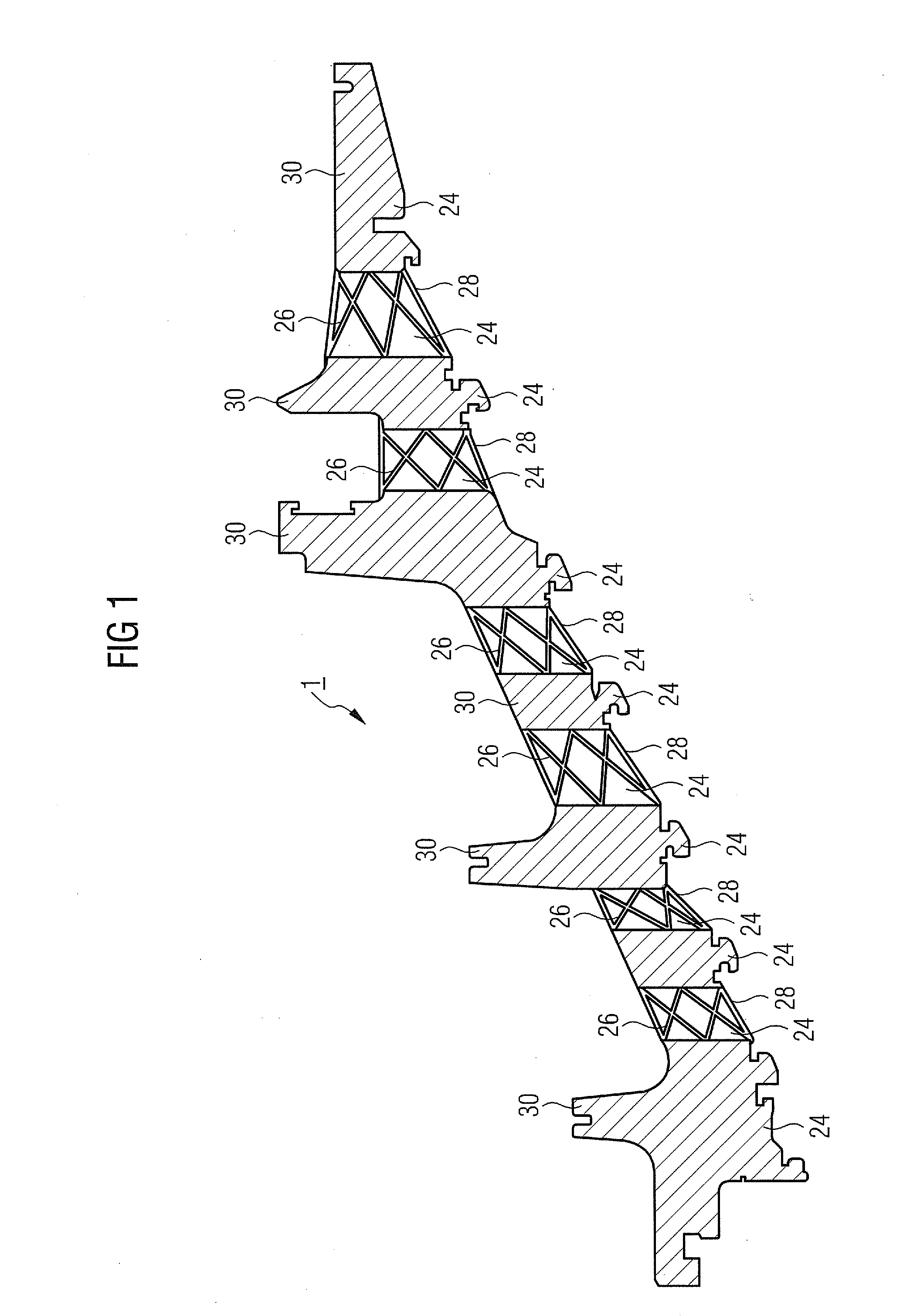
[0026]FIG. 1 shows in detail a half-section through a stator blade carrier 1. In stationary gas turbines, the stator blade carrier 1 is customarily formed conically or cylindrically and consists of two segments, being an upper segment and a lower segment, which are interconnected via flanges, for example. In this case, only the section through the upper segment is shown.

[0027]The stator blade carrier 1 which is shown comprises a number of axial segments 24 which are welded to each other for forming a rigid structure. In order to enable a simpler and lighter construction of the stator blade carrier 1, which, moreover, can be flexibly adapted to the temperature conditions inside the gas turbine 101, a number of axial segments 24 of the stator blade carrier 1 are designed as a lattice construction 26, also referred to as a lattice structure. The lattice constructions 26 are provided in each case on their inner ...


PUM


Abstract

A stator blade carrier for a gas turbine is provided. The stator blade carrier includes a plurality of axial segments. At least one axial segment is designed as a tubular lattice structure. This allows a simpler design technically and a more flexible adaptation to the temperature profile present on the stator blade carrier to maintain operational safety.

Description

CROSS REFERENCE TO RELATED APPLICATIONS[0001]This application is the US National Stage of International Application No. PCT / EP2009 / 061744 filed Sep. 10, 2009 and claims the benefit thereof. The International Application claims the benefits of European application No. 08019365.9 EP filed Nov. 5, 2008. All of the applications are incorporated by reference herein in their entirety.FIELD OF INVENTION[0002]The invention refers to a stator blade carrier—especially for a gas turbine—which consists of a number of axial segments.BACKGROUND OF INVENTION[0003]Gas turbines are used in many fields for driving generators or driven machines. In this case, the energy content of a fuel is used for producing a rotational movement of a turbine shaft. For this, the fuel is combusted in a combustion chamber, wherein compressed air is fed from an air compressor. The operating medium, under high pressure and under high temperature, which is produced in the combustion chamber as a result of combusting the ...

Claims


Application Information

Patent Timeline
Patent Type & Authority Applications(United States)
IPC IPC(8): F04D29/00
CPCF01D25/246F01D9/041
Inventor BRYK, RODERICHDUNGS, SASCHAHARTMANN, MARTINKAHLSTORF, UWEKLEIN, KARLLUSEBRINK, OLIVERMILAZAR, MIRKOSAVILIUS, NICOLASSCHNEIDER, OLIVERSHENG, SHILUNSHEVCHENKO, VADIMSIMON, GERHARDTHAMM, NORBERT
Owner SIEMENS AG
Why Eureka
Try Eureka