Nacelle for a gas turbine engine

Active Publication Date: 2021-06-03
ROLLS ROYCE PLC
View PDF0 Cites 0 Cited by
  • Summary
  • Abstract
  • Description
  • Claims
  • Application Information

AI Technical Summary

Benefits of technology

[0008]The above relationship between the droop angle θdroop and the effective incidence angle of attack α may further reduce the drag on the nacelle.
[0009]In some cases, a combination of the above relationship between the droop angle θdroop and the

Problems solved by technology

Therefore, as the specific thrust reduces, there is a concomitant increase in fan diameter.
This typically results in a nacell

Method used


Image

  • Nacelle for a gas turbine engine
  • Nacelle for a gas turbine engine
  • Nacelle for a gas turbine engine

Examples


Embodiment Construction

[0032]Aspects and embodiments of the present disclosure will now be discussed with reference to the accompanying figures. Further aspects and embodiments will be apparent to those skilled in the art.

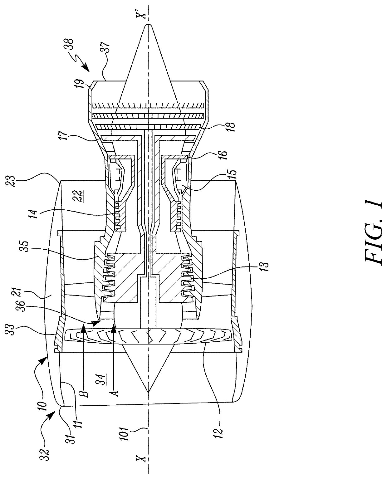
[0033]FIG. 1 shows a ducted fan gas turbine engine 10 having a principal rotational axis X-X′. The principal rotational axis X-X′ coincides with a longitudinal centre line 101 of the gas turbine engine 10.

[0034]In the following disclosure, the following definitions are adopted. The terms “upstream” and “downstream” are considered to be relative to an air flow through the gas turbine engine 10. The terms “axial” and “axially” are considered to relate to the direction of the principal rotational axis X-X′ of the gas turbine engine 10.

[0035]The gas turbine engine 10 includes, in axial flow series, an air intake 11, a propulsive fan 12, an intermediate pressure compressor 13, a high-pressure compressor 14, combustion equipment 15, a high-pressure turbine 16, an intermediate pressure turbine ...


PUM


Abstract

A nacelle for a gas turbine engine having a longitudinal centre line includes an intake lip disposed at an upstream end of the nacelle. The intake lip includes a crown and a keel. The crown includes a crown leading edge and the keel includes a keel leading edge. The crown leading edge and the keel leading edge define a scarf line therebetween. The scarf line forms a scarf angle (θscarf) relative to a reference line perpendicular to the longitudinal centre line. A fan casing is disposed downstream of the intake lip and includes a casing leading edge. The casing leading edge defines a droop line normal to the casing leading edge. The droop line forms a droop angle (θdroop) relative to the longitudinal centre line. A relationship between the droop angle (θdroop) and the scarf angle (θscarf) is given by: θdroopscarf/1.5±1 degree.

Description

CROSS-REFERENCE TO RELATED APPLICATIONS[0001]This specification is based upon and claims the benefit of priority from United Kingdom patent application number GB 1917415.0 filed on Nov. 29, 2019, the entire contents of which is incorporated herein by reference.BACKGROUNDField of the Disclosure[0002]The present disclosure relates to a nacelle and in particular to a nacelle for a gas turbine engine.Description of the Related Art[0003]A gas turbine engine includes a fan housed within a nacelle. Current gas turbine engines generally have a low specific thrust to keep noise at acceptable levels and to achieve low fuel consumption, because a low specific thrust helps to improve specific fuel consumption (SFC). This low specific thrust is usually achieved with a high bypass ratio. Therefore, as the specific thrust reduces, there is a concomitant increase in fan diameter. In order to accommodate a larger diameter fan, dimensions of the nacelle may have to be increased proportionally. This t...

Claims


Application Information

Patent Timeline
IPC IPC(8): F01D9/04F01D25/24F02C7/04
CPCF01D9/04F01D25/24F05D2240/14F05D2220/32F05D2240/12F02C7/04B64D33/02F05D2250/314F05D2260/96B64D2033/0286B64D29/00Y02T50/60
Inventor TEJERO EMBUENA, FERNANDO L.MACMANUS, DAVID G.SHEAF, CHRISTOPHER TJ
Owner ROLLS ROYCE PLC
Why Eureka
Try Eureka