Ceramic heater, sensor element, and gas sensor
a ceramic heater and sensor element technology, applied in the field of ceramic heaters, to achieve the effect of prolonging the life of the heating elemen
- Summary
- Abstract
- Description
- Claims
- Application Information
AI Technical Summary
Benefits of technology
Problems solved by technology
Method used
Image
Examples
examples
[0103]Examples in which sensor elements were specifically manufactured will now be described. Experimental Examples 2 to 9 and 11 to 18 correspond to Examples of the present invention, and Experiment Examples 1 and 10 correspond to Comparative Examples. It should be noted that the invention is not limited to the examples below.
experimental examples 1 to 9
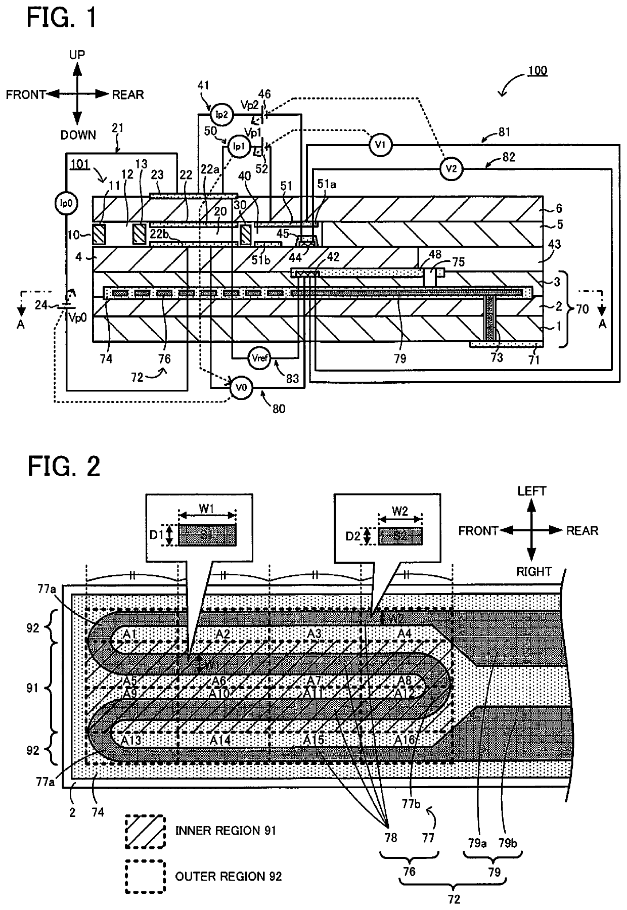
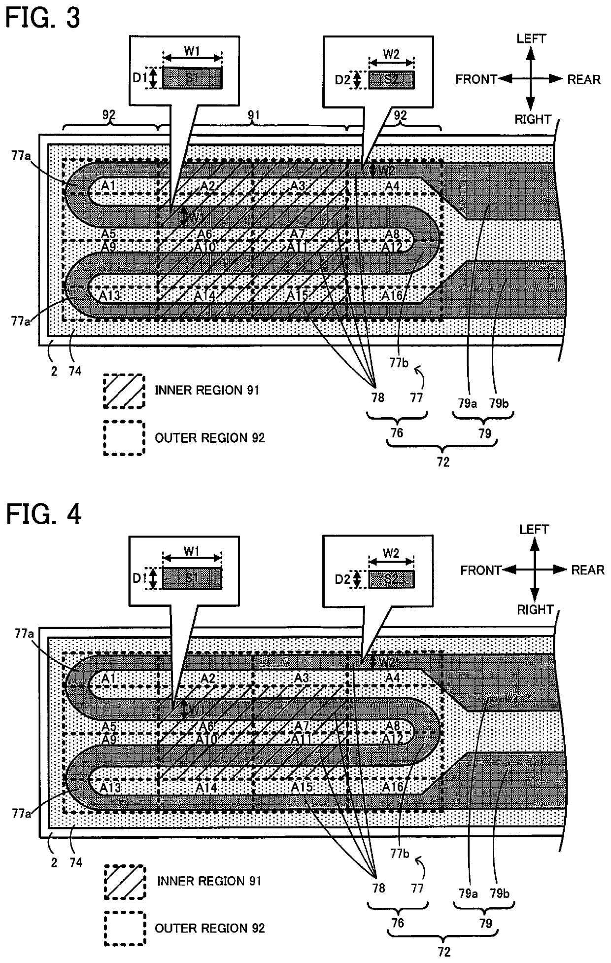
[0104]Sensor elements 101 as shown in FIGS. 1 and 2 were prepared as Experimental Examples 1 to 9 in accordance with the method for manufacturing the gas sensor 100 of the above-described embodiment. Experimental Examples 1 to 9 had the same structure except that the cross-sectional area ratio S2 / S1 in the inner region 91 and the outer regions 92 defined by the first method was varied as shown in Table 1 by varying the width W1 of the inner region 91. The sensor element 101 measured 67.5 mm in length in the front-rear direction, 4.25 mm in width in the left-right direction, and 1.45 mm in thickness in the vertical direction. In Experimental Example 1, the width W1 of the inner region 91 and the width W2 of the outer region 92 were each 0.25 mm. In Experimental Example 1, the thickness D1 of the inner region 91 and the thickness D2 of the outer region 92 were each 0.01 mm. For producing the sensor element 101, ceramic green sheets were formed of a mixture of zirconia particles contai...
experimental examples 10 to 18
[0105]Sensor elements 101 of Experimental Examples 10 to 18 were produced in the same manner as in Experimental Example 1 except that the volume resistivity ratio ρ1 / ρ2 of the inner region 91 and the outer regions 92 defined by the first method was varied as shown in Table 1. The volume resistivity ratio ρ1 / ρ2 was varied by varying the Pt content in the inner region 91. In each of Experimental Examples 10 to 18, widths W1 and W2 and thicknesses D1 and D2 were the same as in Experimental Example 1, and the cross-sectional area ratio S2 / S1 in Experimental Examples 10 to 18 was 1.00. In Experimental Examples 10 and 1, the cross-sectional area ratio S2 / S1 and the volume resistivity ratio ρ1 / ρ2 were the same.
[0106]The volume resistivity ρ1 in Experimental Examples 10 to 18 was measured using test pieces prepared as below. An insulating paste for the heater insulating layer 74 was applied by printing onto a ceramic green sheet that would be sintered into the second substrate layer 2. Subs...
PUM
| Property | Measurement | Unit |
|---|---|---|
| temperature | aaaaa | aaaaa |
| temperatures | aaaaa | aaaaa |
| length | aaaaa | aaaaa |
Abstract
Description
Claims
Application Information
 - R&D
- Intellectual Property
- Life Sciences
- Materials
- Tech Scout
- Unparalleled Data Quality
- Higher Quality Content
- 60% Fewer Hallucinations
Browse by: Latest US Patents, China's latest patents, Technical Efficacy Thesaurus, Application Domain, Technology Topic, Popular Technical Reports.
© 2025 PatSnap. All rights reserved.Legal|Privacy policy|Modern Slavery Act Transparency Statement|Sitemap|About US| Contact US: help@patsnap.com


