Fixing element for electrical devices

a technology for fixing elements and electrical devices, applied in the direction of transmission, alarms, transmission systems, etc., can solve problems such as limiting the available construction spa

Active Publication Date: 2020-11-17
BALLUFF
View PDF15 Cites 0 Cited by
  • Summary
  • Abstract
  • Description
  • Claims
  • Application Information

AI Technical Summary

Benefits of technology

[0008]The fixing element according to the invention offers the advantage that a direct cabling or an electromechanical contact to the at least one electrical device is not necessary. In particular with a multitude of electrical devices, on one hand, this leads to a simplification of the installation, while on the other hand, the number of usually obstructive cables or lines is reduced. At most, a cabling of the fixing element must take place, wherein, to do so, reference is made to versions explained further below. Furthermore, the at least one electrical device can be rearranged quickly and with less effort. In addition, such a fixing element enables a hygienic design, since contact points, for example for cable connections or for electromagnetic contacts, are avoided, on which contamination could form.
[0028]Furthermore, the signal preparation device can be set up to find a contamination which has collected on the fixing element by means of the capacitive and / or inductive coupling. The contamination reduces the coupling strength, such that this can be used as a measure for the contamination.

Problems solved by technology

Along with the large amount of time expenditure when installing, deconstructing and exchanging, the cable connection or the electromechanical contacting limits the available construction space, since cables or electrical lines must always be led to the electrical devices.
In particular in the field of hygiene, there is a further disadvantage since contamination can be facilitated as a result of the contact points.

Method used


Image

  • Fixing element for electrical devices
  • Fixing element for electrical devices
  • Fixing element for electrical devices

Examples


first embodiment

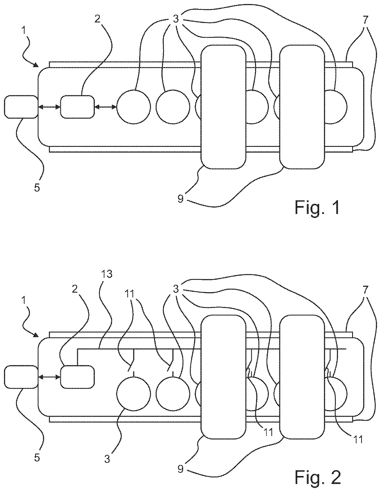
[0050]FIG. 1 shows a schematic depiction of the equipment according to the invention having the fixing element 1 according to the invention for sensors 9 in the form of a straight, cylindrical rod and two sensors 9, which are fixed on a fixing portion 7 on the outside, more exactly on the lateral surface, of the fixing element 1, by means of a fixing means, for example a mechanical clamping element or a magnetic holding element, which is not shown here in more detail. The sensors 9 can be arranged in any position and in any orientation on the lateral surface of the fixing element 1. The fixing element has six electromagnetic couplers 3 in its inside, which are arranged equidistantly one following the other in a row along the axial direction, i.e. the central axis. The couplers 3 are formed on a board not shown here in more detail, which is part of the fixing element 1 and is arranged inside the fixing element 1, wherein components of the couplers 3 are implemented by means of conduc...

fifth embodiment

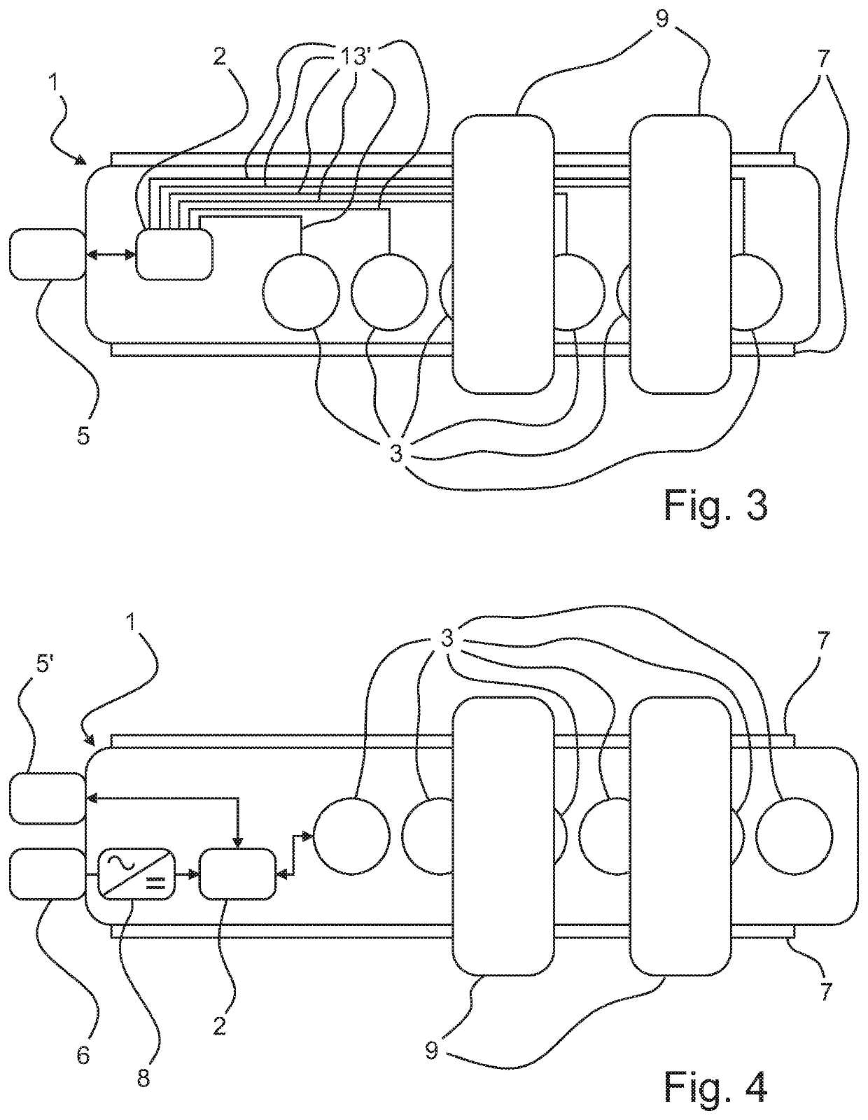
[0058]FIG. 5 shows a schematic depiction of the fixing element 1 according to the invention having an adapter 91, which is connected to a sensor 9. The adapter 91 is fixed to a fixing portion 7 on the outside, more exactly on the lateral surface, of the fixing element 1 by means of a fixing means not depicted in more detail here, for example a mechanical clamping element or a magnetic holding element. The adapter 91 has an adapter port 92, via which the sensor 9 is connected to the adapter 91. In this embodiment, the adapter port 92 is set up as an interface both for transmitting the electrical energy to the sensor and for a digital communication, via which data are transferred to the sensor 9 or from the sensor 9. In a preferred embodiment, the port 5 is set up for an IO-link communication. Furthermore, a sealing ring 93 is provided, which is arranged between the adapter 91 and the sensor 9 and lies around the adapter port 92, whereby it seals the connection point between the adapt...

sixth embodiment

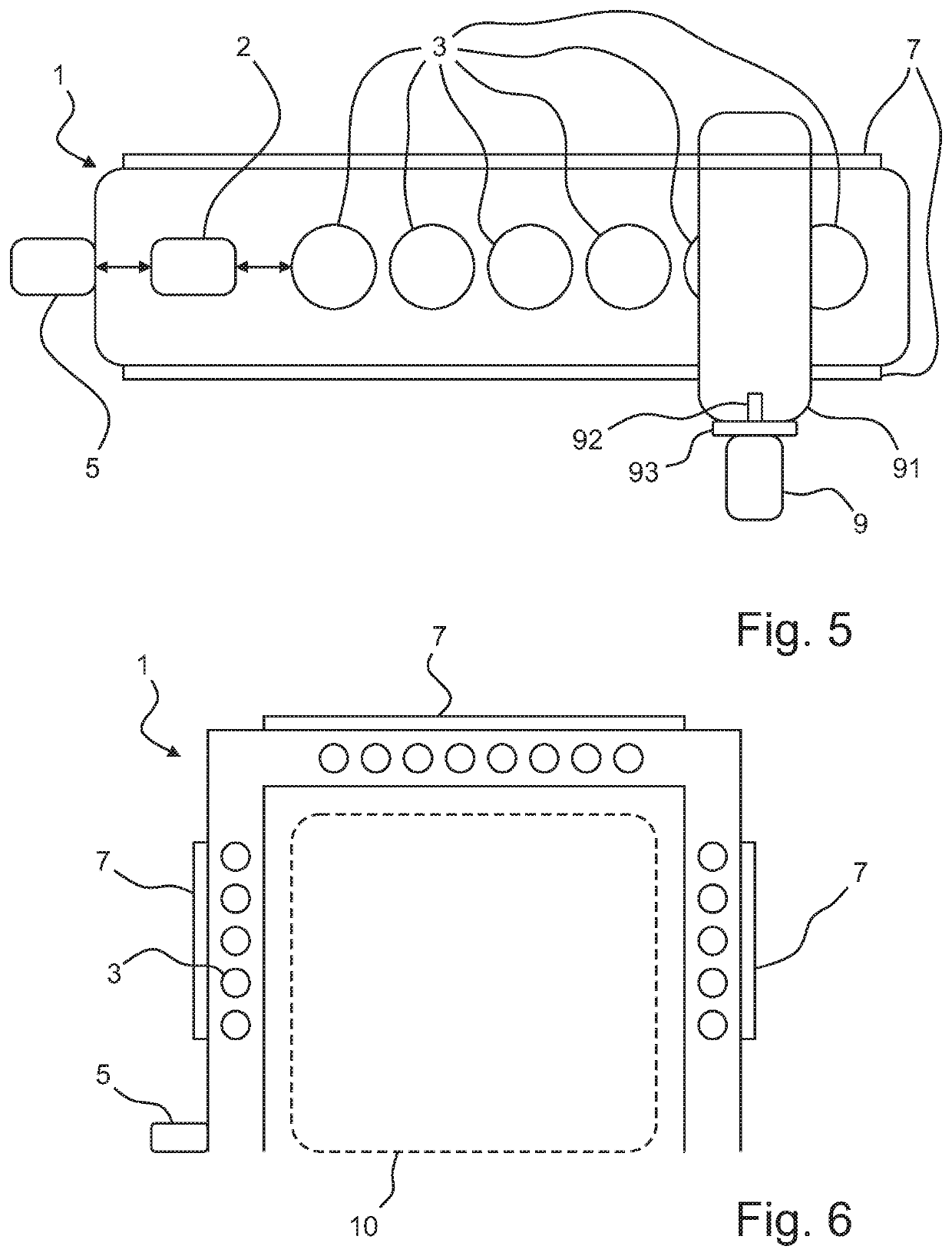
[0059]FIG. 6 shows a schematic depiction of the fixing element 1 according to the invention, which is formed as a rod bent twice, wherein both of the bends are formed in such a way that the central axis of the bent rod further lies on a plane. The features of the components described above can be assumed for this embodiment. Here, the board not shown can be formed as a flexible circuit board having FlexPrint as a flexible base material. Because of the twice curved, planar design of the fixing element 1, a region enclosed in a U-shape is formed, in which the measuring region 10 of the sensors 9 not depicted here is arranged. Furthermore, the couplers 3 are arranged one following the other along the curved central axis of the bent rod and are arranged on a plane.


PUM


Abstract

A fixing element for electrical devices, wherein at least one electrical device can be fixed to the fixing element, has at least one coupler, which forms at least one coupling to the at least one electrical device fixed to the fixing element, via which coupling electrical energy and / or data can be transmitted to the at least one electrical device, wherein the coupling is a capacitive and / or inductive coupling. In addition, equipment includes such a fixing element and a least one electrical device, which is fixed to the electrical element.

Description

CROSS REFERENCE TO RELATED APPLICATIONS[0001]Applicant claims priority under 35 U.S.C. § 119 of German Application No. 10 2018 109 267.9 filed Apr. 18, 2018, the disclosure of which is incorporated by reference.BACKGROUND OF THE INVENTION1. Field of the Invention[0002]The present invention relates to a fixing element for electrical devices, in particular sensors and / or actuators, via which fixing element electrical energy and / or data can be transmitted to the electrical device. Furthermore, the present invention relates to an equipment having such a fixing element and at least one electrical device. Such a fixing element can be used, for example, in the field of hygiene.2. Description of the Related Art[0003]Traditionally, electrical devices are fixed on fixing elements, usually in fixed positions, wherein the electrical devices are arranged at predetermined locations by means of the fixing elements. Rods are used as typical fixing elements, wherein the electrical devices are usuall...

Claims


Application Information

Patent Timeline
Patent Type & Authority Patents(United States)
IPC IPC(8): G08B21/18H02J50/05G01P1/00H02J50/10F16B1/00H04W84/18
CPCH02J50/10G08B21/182H02J50/05G01P1/00H04W84/18F16B1/00F16B2001/0035H04B5/0031H04B5/0037H04B5/0081H04B5/0012G08C17/02G08C17/06H02J50/40H02J50/90H04B5/0075F16B2200/83
Inventor GAGGERO, PASCALWOHLFART, ELLENSCHMIDT, MANUELA
Owner BALLUFF
Why Eureka
Try Eureka