
Electrical conductor comprised of solid segments

a technology of electrical conductors and solid segments, applied in the manufacture of cables/conductors, power cables, conductors, etc., can solve the problems of affecting the affecting the effect of local current-carrying capacity or local electrical resistance, and undesirable gases in the interior of the conductor, so as to achieve effective electrical cross-section, reduce or prevent any separation of the electrical conductor, and achieve the effect of effective fulfillment of the function

Active Publication Date: 2020-11-17
NEXANS
View PDF9 Cites 1 Cited by
  • Summary
  • Abstract
  • Description
  • Claims
  • Application Information

AI Technical Summary

Benefits of technology

This configuration provides an electrical conductor with an optimal effective cross-section and enhanced flexibility, preventing fluid penetration and corrosion while reducing the force required for bending, thus addressing the limitations of single-core solid conductors.

Problems solved by technology

In solid electrical conductors of large cross-section, in particular during laying, any potential bending required is problematic, as the conductor material is stretched on the outer radius of the bent conductor section, and is compressed on the inner radius of the bent conductor section.
However, stretching and compression alter the cross-section of the conductor, and consequently affect the local current-carrying capacity or the local electrical resistance.
Liquid or vapour, but also gases in the interior of a conductor are undesirable, on the grounds of the risk of corrosion and the associated impairment of conductivity, and on the grounds of the impairment of the properties of insulation.
The process and controls for the complete filling of the gaps, or for the swelling capability of the material employed, are complex.
However, this arrangement increases the diameter of the conductor bundle, on the grounds of the presence of additional regions which are not available for the transmission of current, with the above-mentioned consequences.
Moreover, the insulation is subject to mechanical loading during stranding, and may sustain damage.
In DC transmission, however, which is increasingly employed, particularly in the e.h.v. range, the skin effect plays no role, such that the necessary complexity of technical production and the additional material expenditure are of greater importance.

Method used


Image

  • Electrical conductor comprised of solid segments

Examples


Embodiment Construction

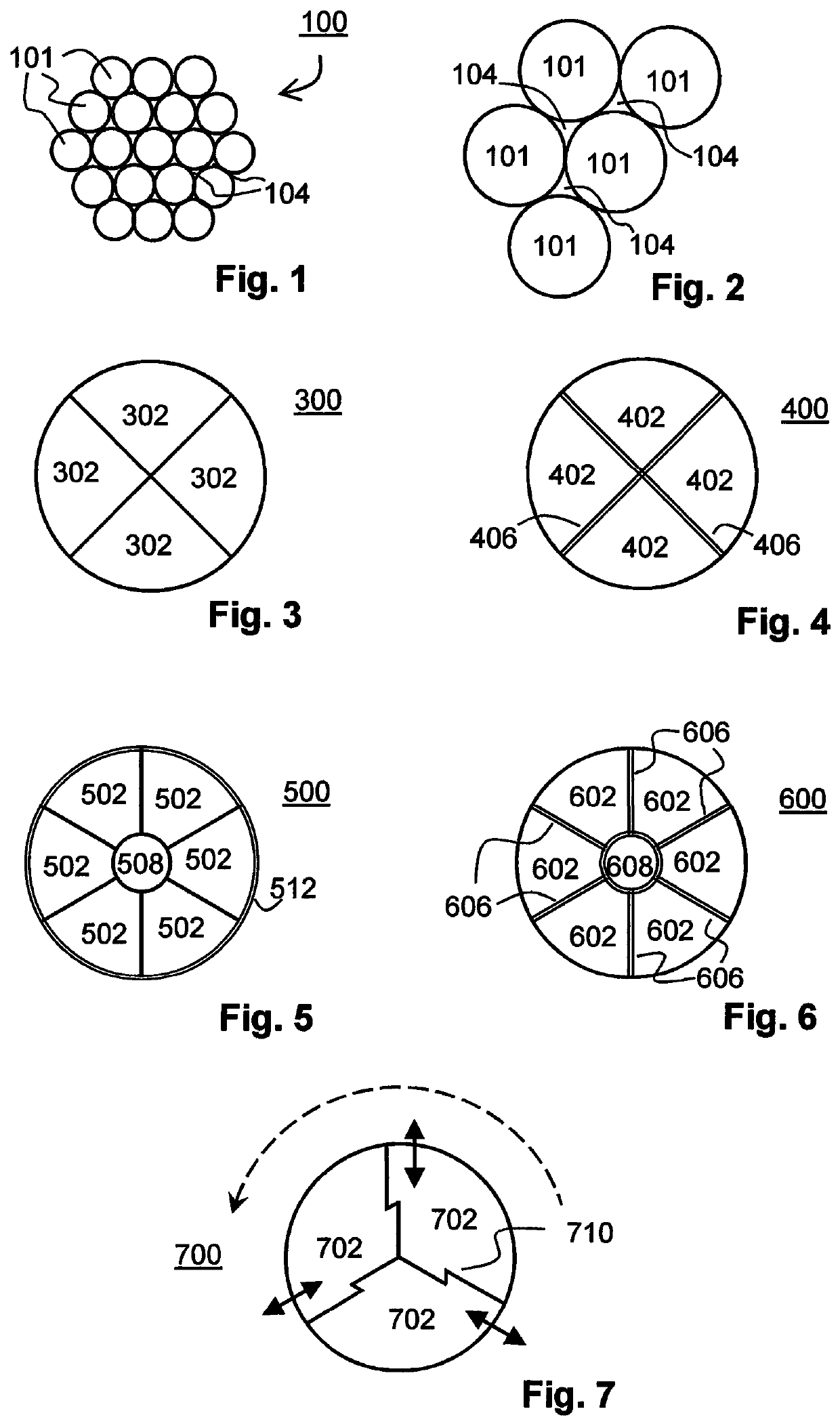
[0037]FIG. 3 shows a cross-section of a first exemplary electrical conductor 300 according to the invention, having four solid segments 302 of identical shape. Although, in this example, the segments are of equal size, the employment of segments of different sizes is also conceivable. In this case, it can be expedient to execute initial and terminal contacting such that, insofar as possible, the current density relative to the cross-sectional area of each segment is identical, in order to prevent different current densities in the event of poor electrical contact between the individual segments arranged along the electrical conductor.

[0038]FIG. 4 shows a cross-section of a second exemplary electrical conductor 400 according to the invention, having four solid segments 402 of identical size which are separated by a separating layer 406. As described above, the separating layer can be electrically conductive or non-conductive, and can be comprised of a material which swells upon conta...


PUM

PropertyMeasurementUnit
electricalaaaaaaaaaa
shapeaaaaaaaaaa
electrically conductiveaaaaaaaaaa

Abstract

An electrical conductor comprises three or more solid segments of identical shape. In cross-section, each segment comprises two sides, which are configured for flush bearing against correspondingly opposing lateral surfaces on another segment. The cross-sectional surface through all the constituent segments of the electrical conductor is describable by a closed curve having a stepless characteristic. All the constituent segments of the electrical conductor are stranded in combination.

Description

RELATED APPLICATION[0001]This application claims the benefit of priority from European Patent Application No. 17 306 768.7, filed on Dec. 13, 2017, the entirety of which is incorporated by reference.FIELD[0002]The invention relates to an electrical conductor, specifically for high direct currents.BACKGROUND[0003]Electrical conductors are employed in a variety of applications, for example for the transmission of electrical energy or the transmission of information or data represented by electrical signals.[0004]Electrical conductors for the transmission of electrical energy in the form of a direct or alternating current and a DC or AC voltage, respectively, must be adapted to the maximum power which is to be transmitted via the conductor. The electric power, in simple terms, can be expressed as the product of the voltage and current. The effective cross-section of the electrical conductor, i.e. the cross-section of the conductor which is actually available for the transmission of cur...

Claims


Application Information

Patent Timeline
Patent Type & Authority Patents(United States)
IPC IPC(8): H01B5/00H01B7/282H01B7/10H01B9/00H01B7/40H01B7/288H01B13/02
CPCH01B9/006H01B7/2825H01B7/40H01B7/10H01B7/288H01B13/02H01B5/08H01B5/10H01B5/101Y02A30/14H01B5/00
Inventor MENGER, MICHAELVOIGT, TORSTENGAULER, VOLKER
Owner NEXANS
Learn More