
Light guide plate, planar light source apparatus, display apparatus, and electronic device

a light guide and planar light source technology, applied in the direction of light guide plates, planar/plate-like light guides, lighting and heating devices, etc., can solve the problem of easy non-uniformity of light guide plates between portions, and achieve the effect of suppressing non-uniformity of light guide plates and promoting the thickness reduction of light guide plates

Active Publication Date: 2020-11-24
NICHIA CORP
View PDF19 Cites 0 Cited by
  • Summary
  • Abstract
  • Description
  • Claims
  • Application Information

AI Technical Summary

Benefits of technology

The invention reduces the thickness of a light guide plate and suppresses brightness non-uniformity.

Problems solved by technology

In the case of a direct-type backlight, while a plurality of LEDs are arranged directly underneath a light guide plate, brightness non-uniformity easily occurs on the light guide plate between portions directly above the LEDs and other portions.

Method used


Image

  • Light guide plate, planar light source apparatus, display apparatus, and electronic device
  • Light guide plate, planar light source apparatus, display apparatus, and electronic device
  • Light guide plate, planar light source apparatus, display apparatus, and electronic device

Examples


Embodiment Construction

[0035]Hereinafter, an embodiment of the present invention will be described with reference to the drawings. It is to be understood that the embodiment described below merely represents an example of implementing the present invention and is not intended to limit the present invention to the specific configurations described hereinafter.

[0036]In the embodiment described below, the “display apparatus” will be described as a liquid crystal display apparatus and the “planar light source apparatus” will be described as a backlight of the liquid crystal display apparatus. The “planar light source apparatus” can be used for applications other than a backlight such as a front light arranged in a front surface of a display panel or an electronic paper-based display apparatus.

(Configuration of Liquid Crystal Display Apparatus)

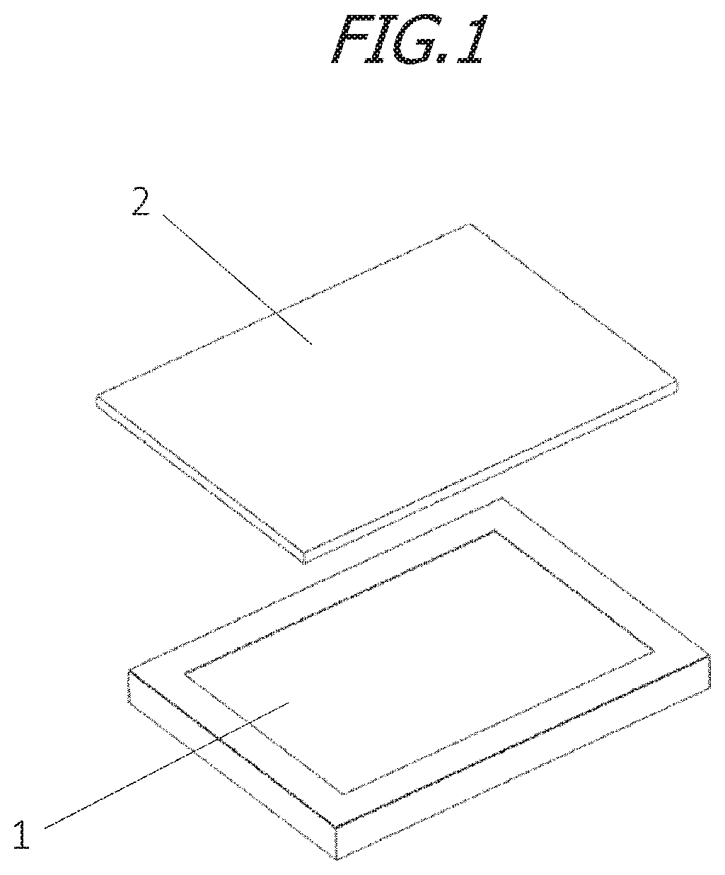
[0037]FIG. 1 is a perspective view illustrating a configuration of a liquid crystal display apparatus according to the embodiment. As shown in FIG. 1, the liquid crystal...


PUM

PropertyMeasurementUnit
angleaaaaaaaaaa
thicknessaaaaaaaaaa
diameteraaaaaaaaaa

Abstract

An object is to promote a reduction in thickness of a light guide plate and suppress brightness non-uniformity of the light guide plate. A light guide plate, including: a light exit surface from which light is emitted; an opposite surface on an opposite side of the light exit surface; a depressed portion provided on the opposite surface; and a plurality of scattering portions which are provided on the light exit surface, the opposite surface, and a bottom surface of the depressed portion and which refract and scatter light, wherein the depressed portion has a tapered surface which spreads from the bottom surface of the depressed portion toward an opening of the depressed portion.

Description

TECHNICAL FIELD[0001]The present invention relates to a light guide plate, a planar light source apparatus, a display apparatus, and an electronic device.BACKGROUND ART[0002]In recent years, advances have been made in reducing sizes and thicknesses of electronic devices. There are demands for a reduction in a thickness of a light guide plate of a liquid crystal display apparatus (a liquid crystal display) to be mounted to such electronic devices. Backlight systems for liquid crystal display apparatuses include a system referred to as an edge light-type backlight and a system referred to as a direct-type backlight. Direct-type backlights which feature high light utilization efficiency and which enable higher brightness to be readily achieved are used as backlights for large-size liquid crystal display apparatuses. For example, an LED (Light Emitting Diode) which emits white light is used as a light source of a backlight. In the case of a direct-type backlight, while a plurality of LE...

Claims


Application Information

Patent Timeline
Patent Type & Authority Patents(United States)
IPC IPC(8): G09F13/04G09F13/08F21V8/00G02F1/01G02F1/13357
CPCG02F1/0107G02B6/0016G02B6/0028G02F1/133603G02B6/0011G02F1/133524G02F1/133608G02F1/133606F21S2/00G02B6/0021G02B6/0043G02F1/133607G02F1/1335G02B6/005
Inventor WATANABE, SHOTAROHIROTA, KAZUHIDEISHIMI, NAOKI
Owner NICHIA CORP
Learn More