Method and device for transferring a decorating segment of an embossing film

a technology of embossing film and decorating section, which is applied in the direction of printing, decorative arts, rotary presses, etc., can solve the problems of contamination of machinery, no separating edge at all, and the difficulty of stamping to produce a clean separating edge, so as to achieve the effect of cleaning the decorative section

Active Publication Date: 2020-12-22
HINDERER MUHLICH GMBH & CO KG +1
View PDF18 Cites 0 Cited by
  • Summary
  • Abstract
  • Description
  • Claims
  • Application Information

AI Technical Summary

Benefits of technology

[0005]The object of the present invention is to provide an improved method which combines the advantages of a stable stamping foil with the clean separation of the decorative sections from the carrier film.

Problems solved by technology

During the application of stamping foils which contain in the lacquer package in particular strongly crosslinking lacquer systems, for example UV-crosslinking lacquer systems and / or lacquer systems with a high layer thickness, i.e. with a thickness of the transfer ply without carrier film greater than 5 μm, a clean separating edge can only be produced with great difficulty during stamping.
A comparatively soft and elastic lacquer, for example, may not break or only break incompletely, or tear in an undefined way during stamping with the result that, at worst, no separating edge at all is formed.
Normally, during stampings of this kind, stray residues of the transfer ply formed as lacquer package, the aforementioned so-called flakes, are formed, which during further processing of the stamped substrate lead to contamination of the machinery and thus to increased cleaning effort.
In extreme cases, production waste can be significantly increased by these flakes.
Without adhering to the substrate, the flakes are attached to the parts of a decorative section applied to the substrate adhering to the substrate and, during further processing, can either remain attached thereto or tear off in an uncontrolled manner and thereby cause corresponding problems in the processing of the stamping foil and / or of the substrate.

Method used


Image

  • Method and device for transferring a decorating segment of an embossing film
  • Method and device for transferring a decorating segment of an embossing film
  • Method and device for transferring a decorating segment of an embossing film

Examples


Embodiment Construction

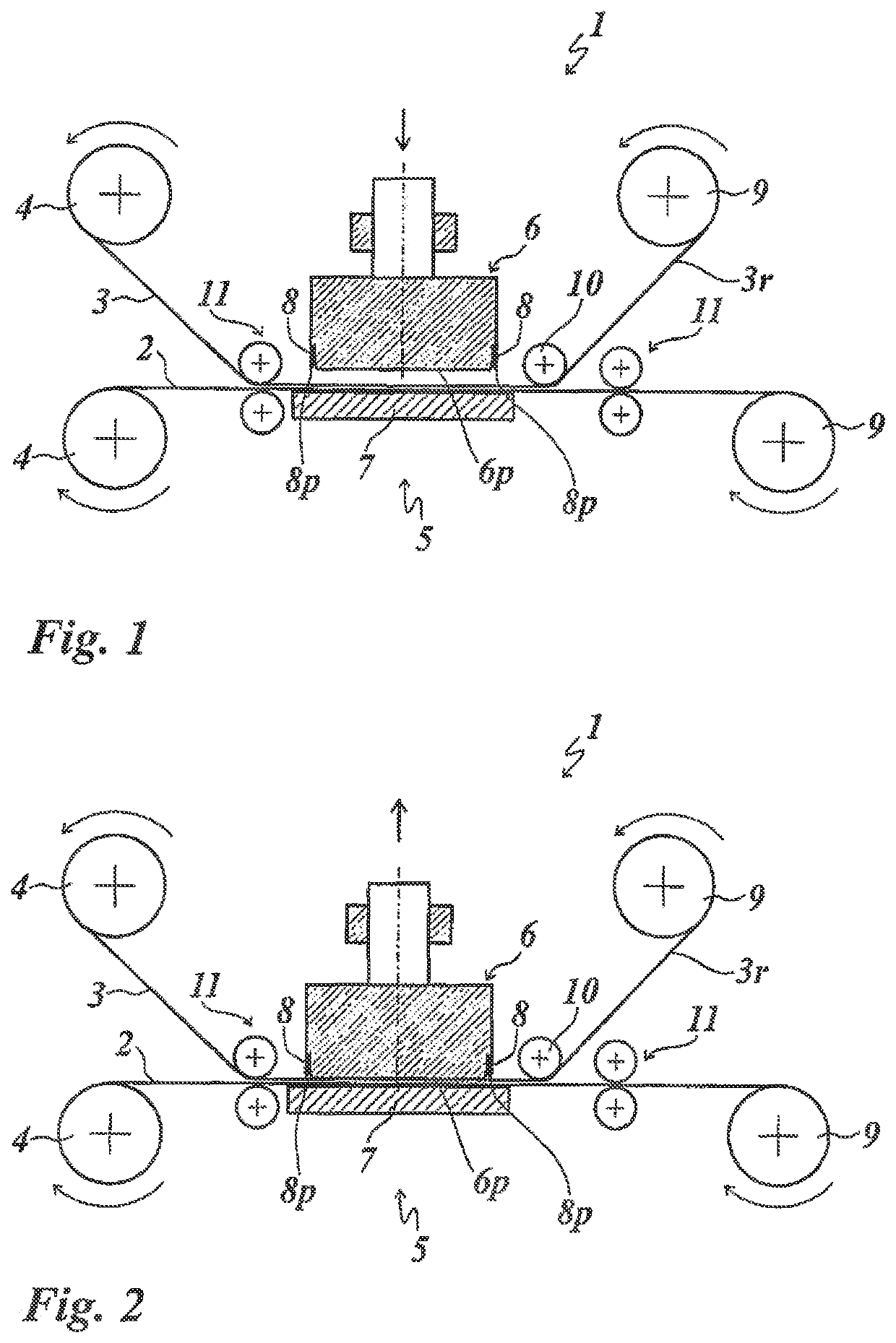
[0059]FIGS. 1 and 2 show a first embodiment example of the stamping device 1 according to the invention in a schematic representation;

[0060]In the embodiment shown, the stamping device 1 is formed as a lifting stamping device and for the roll-to-roll method, in which both a substrate 2 to be embossed and a stamping foil 3 are provided on supply rolls 4.

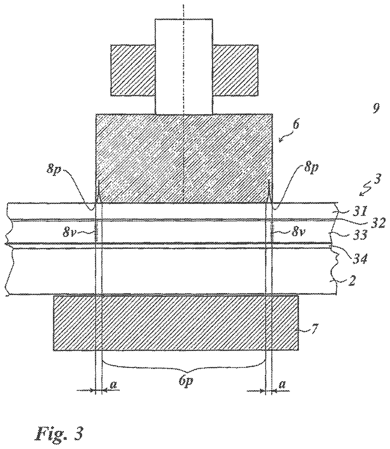
[0061]The stamping foil 3 comprises a carrier film 31, a detachment layer 32, a transfer ply 33 and an adhesive layer 34 (see FIG. 3). The structure of the stamping foil 3 is described in more detail in FIG. 9 below.

[0062]The stamping foil 3 and the substrate 2 are fed to a stamping station 5 with a vertically movable embossing die 6, wherein the substrate 2 lies with its underside on a stamping support 7 in the stamping station 5. The stamping foil 3 lies with its adhesive layer 34 on the top of the substrate 2. Alternatively (not shown), the embossing die can also be formed as a rolling stamping wheel or as a curved embossing die ro...


PUM

PropertyMeasurementUnit
widthaaaaaaaaaa
thicknessaaaaaaaaaa
widthaaaaaaaaaa

Abstract

A method for transferring a decorative section of a stamping foil onto a substrate by means of an embossing die, wherein the stamping foil includes a carrier film and a transfer ply arranged on the carrier film. The method includes:
  • a) Provision of the stamping foil;
  • b) Embossing or pressing of at least one compression section spaced apart from the edge of the decorative section, into the transfer ply;
  • c) Stamping of the decorative section onto the substrate;
  • d) Detachment of the residual stamping film from the substrate embossed with the decorative section.

Description

[0001]This application claims priority based on an International Application filed under the Patent Cooperation Treaty, PCT / EP2016 / 062291, filed May 31, 2016, which claims priority to DE102015110077.0, filed Jun. 23, 2015, DE102015116514.7, filed Sep. 29, 2015 and DE102015119888.6, filed Nov. 17, 2015.BACKGROUND OF THE INVENTION[0002]The invention relates to a method and a device for transferring a decorative section of a stamping foil onto a substrate.[0003]During the application of stamping foils which contain in the lacquer package in particular strongly crosslinking lacquer systems, for example UV-crosslinking lacquer systems and / or lacquer systems with a high layer thickness, i.e. with a thickness of the transfer ply without carrier film greater than 5 μm, a clean separating edge can only be produced with great difficulty during stamping. In addition, in these cases the separation of the film composite does not take place at the edge of the application tool, but at an undefined...

Claims


Application Information

Patent Timeline
Patent Type & Authority Patents(United States)
IPC IPC(8): B44B5/00B44C1/17B44B5/02B41F19/06
CPCB44B5/028B44C1/1729B41F19/068B44B5/02
Inventor AMMON, GERHARDMANNSFELD, TIBORBURKHARDT, MARKUSLOCHNER, THOMAS
Owner HINDERER MUHLICH GMBH & CO KG
Why Eureka
Try Eureka