Sensorized axle box-bearing unit for supporting a railway axle

a technology for railway axles and box bearings, which is applied in the direction of bearing unit rigid support, mechanical equipment, transportation and packaging, etc., can solve the problems of reduced assembly efficiency, reduced service life, and reduced service life of sensors, so as to prevent potential interference, prevent potential interference, and ensure the effect of reliable sealing

Active Publication Date: 2020-12-22
AB SKF
View PDF20 Cites 0 Cited by
  • Summary
  • Abstract
  • Description
  • Claims
  • Application Information

AI Technical Summary

Benefits of technology

[0005]The present invention is intended to provide a sensorized axle box-bearing unit for supporting a railway axle that addresses the aforementioned drawbacks, and that in particular is easy to assemble, that provides a reliable seal against external contaminants, and that prevents potential interference between the electrical data-transmission cable of the sensor unit and moveable parts of the axle box-bearing unit.

Problems solved by technology

Firstly, the sensor unit, due to the presence of the flanged portion, is relatively costly and complex to manufacture, and is particularly difficult to assemble since the flanged portion is liable to interfere with other elements of the axle when inserting the sensor unit into the housing element, or in any case is liable to hinder such insertion, in particular where space is limited.
Secondly, the seal against potential external contaminants provided by the sensor unit may be less than perfect, thereby potentially enabling moisture to enter the housing element.
Thirdly, an electrical data-transmission cable that is part of the sensor unit and that connects the sensor module to a connection piece for sending data to an electronic processing unit may, in use, become entangled with or in any case interfere with the journal or other moving parts of the unit.

Method used


Image

  • Sensorized axle box-bearing unit for supporting a railway axle
  • Sensorized axle box-bearing unit for supporting a railway axle
  • Sensorized axle box-bearing unit for supporting a railway axle

Examples


Embodiment Construction

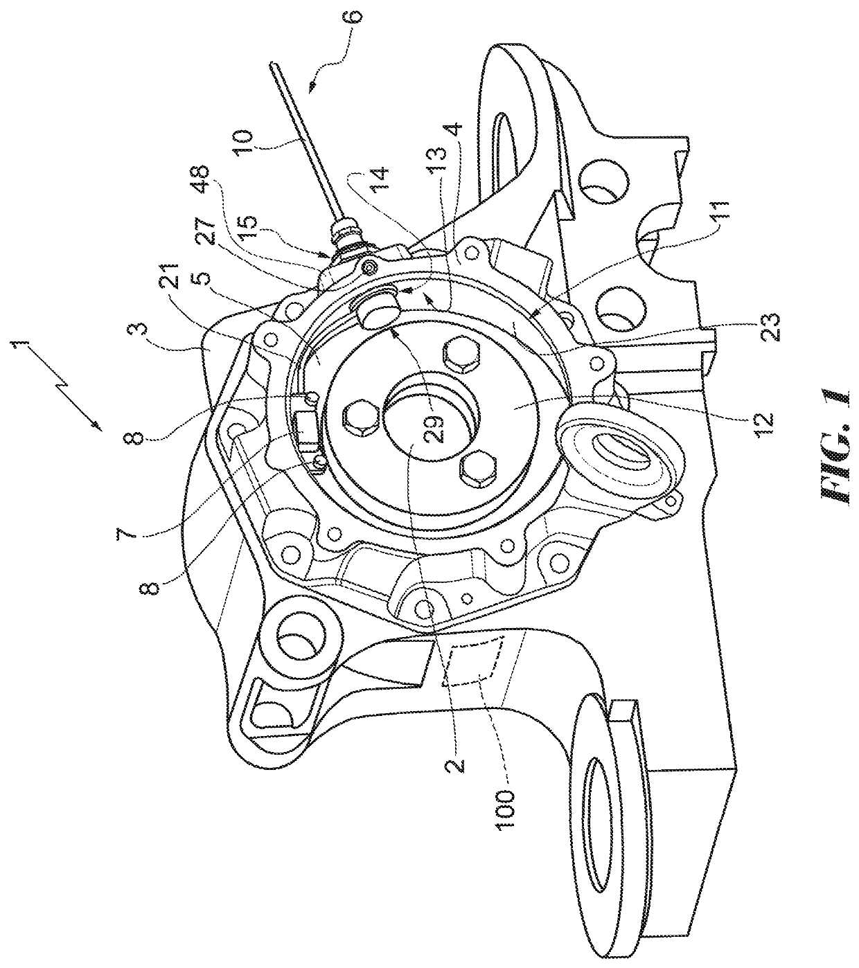
[0014]In FIGS. 1 to 3, reference sign 1 indicates (as a whole) a sensorized axle box-bearing unit for supporting an axle 2 of a railway vehicle, that is of a known type and as such, for the sake of simplicity, is not shown in detail.

[0015]The unit 1 includes a railway axle box 3 designed to rotatably contain one extremity of reduced-diameter or journal of the axle 2 by means of a rolling bearing 100, which is known and illustrated only partially using hatching for the sake of simplicity, which in turn comprises an inner ring that can be assembled on the journal and an outer ring that is rigidly connected to a housing element 4 of the axle box 3 and that is stationary when in use, that, in the non-limiting the example shown, also includes a sealing ring 5 positioned towards the outside of the axle box 3 and about the axle 2 that is intended to protect the rolling bearing 100.

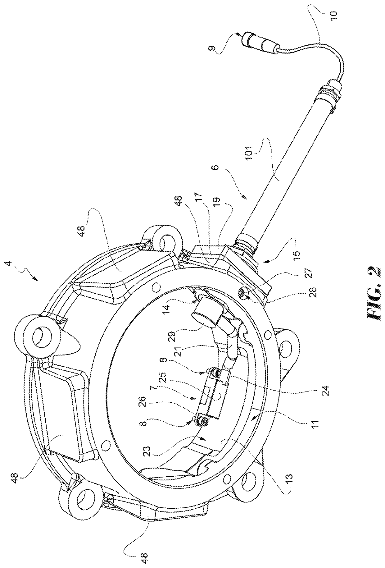
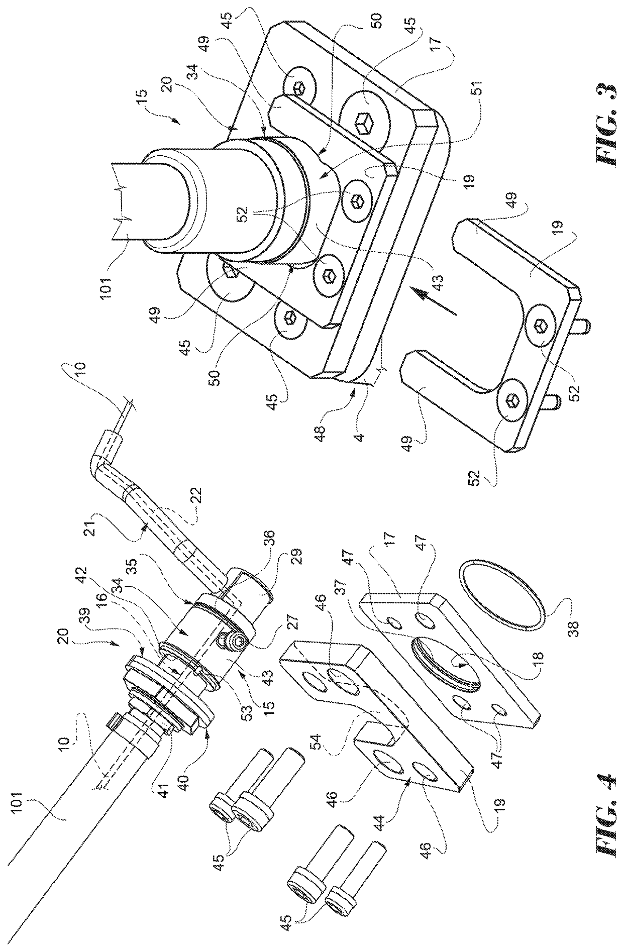
[0016]The axle box-bearing unit 1 also includes a sensor unit 6 in turn including a sensor module 7 assembled ...


PUM


Abstract

An axle box-bearing unit for an axle including a housing element and a sensor unit having a sensor module, a connection piece for connecting to a processing unit and a flexible electrical cable joining the sensor module and the connection piece into a single part. The housing element is delimited by an annular lateral wall provided with a transversal through hole engaged by a plug fitted in a fluid-tight manner to the flexible electrical cable between the sensor module and the connection piece. A first plate provided with a second through hole is rigidly connected to the lateral wall of the housing element, with the second hole aligned with the first hole and crossed through by the plug, a second U-shaped plate is fitted astride of the plug to connect with one end of same that projects radially from the holes and is rigidly connected to the first plate.

Description

CROSS REFERENCE TO RELATED APPLICATIONS[0001]This application claims priority to Italian patent application no. 102016000033785 filed on Apr. 1, 2015, the contents of which are fully incorporated herein by reference.FIELD OF THE INVENTION[0002]The present invention relates to a sensorized axle box-bearing unit for supporting a railway axle.BACKGROUND OF THE INVENTION[0003]As is known, for example from U.S. Pat. No. 3,741,614, a railway vehicle is supported by a series of axles onto which the wheels are press fitted. Each end of the axle is supported rotatably by a axle box-bearing unit comprising an axle box connected using appropriate suspension means to the railway carriage and a rolling bearing. An inner ring of the rolling bearing is rigidly attached to one end of lesser diameter of the axle, referred to as the journal, and rotates with same, while an outer ring of the rolling bearing is positioned inside a housing element of the axle box, which is generally annular and stationa...

Claims


Application Information

Patent Timeline
Patent Type & Authority Patents(United States)
IPC IPC(8): B61F15/20F16C35/04B61F5/20F16C41/00
CPCB61F5/20F16C41/008B61F15/20F16C35/042F16C2233/00F16C2326/10B61F15/12F16C35/04F16C41/00G01M13/04
Inventor ROSSI, MARIOMAZZARINO, ALBERTOROBERTI, ANDREAVANA, RICCARDO
Owner AB SKF
Why Eureka
Try Eureka