Adaptable high-performance extrusion head for fused filament fabrication systems

a high-performance, extrusion head technology, applied in the direction of additive manufacturing processes, manufacturing tools, applying layer means, etc., can solve the problems of cap temperature limitation, cap and seal leakage, etc., and achieve the effect of reducing upstream heat transfer

Active Publication Date: 2020-12-29
SLICE ENG LLC
View PDF19 Cites 3 Cited by
  • Summary
  • Abstract
  • Description
  • Claims
  • Application Information

AI Technical Summary

Benefits of technology

[0016]The cooler is thermally coupled with the upstream portion for reducing upstream heat transfer. The cooler is spaced generally axially from the heater to define a generally axially extending gap traversed by the feed tube.

Problems solved by technology

These caps have temperature limitations and require a sealing mechanism between the cap and the heating body, which is typically formed of aluminum.
The caps and seal are prone to leakage.

Method used


Image

  • Adaptable high-performance extrusion head for fused filament fabrication systems
  • Adaptable high-performance extrusion head for fused filament fabrication systems
  • Adaptable high-performance extrusion head for fused filament fabrication systems

Examples


Embodiment Construction

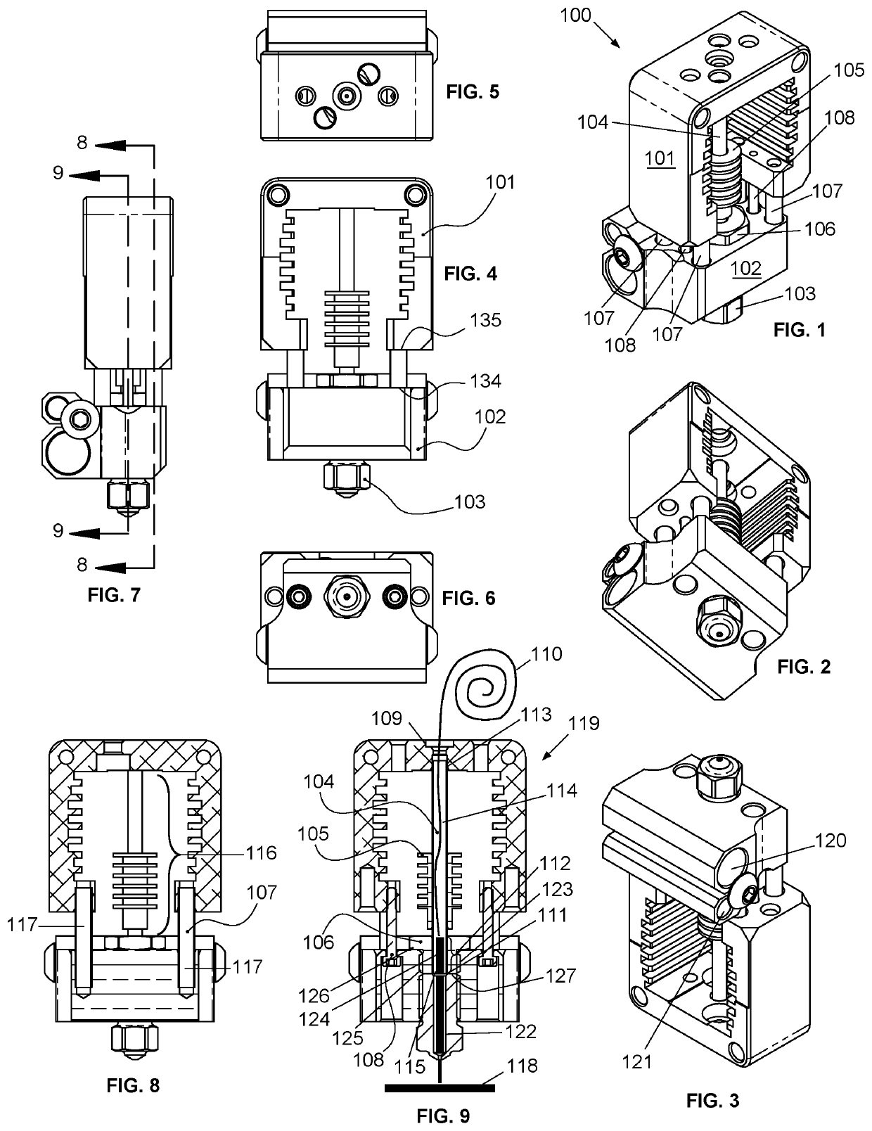
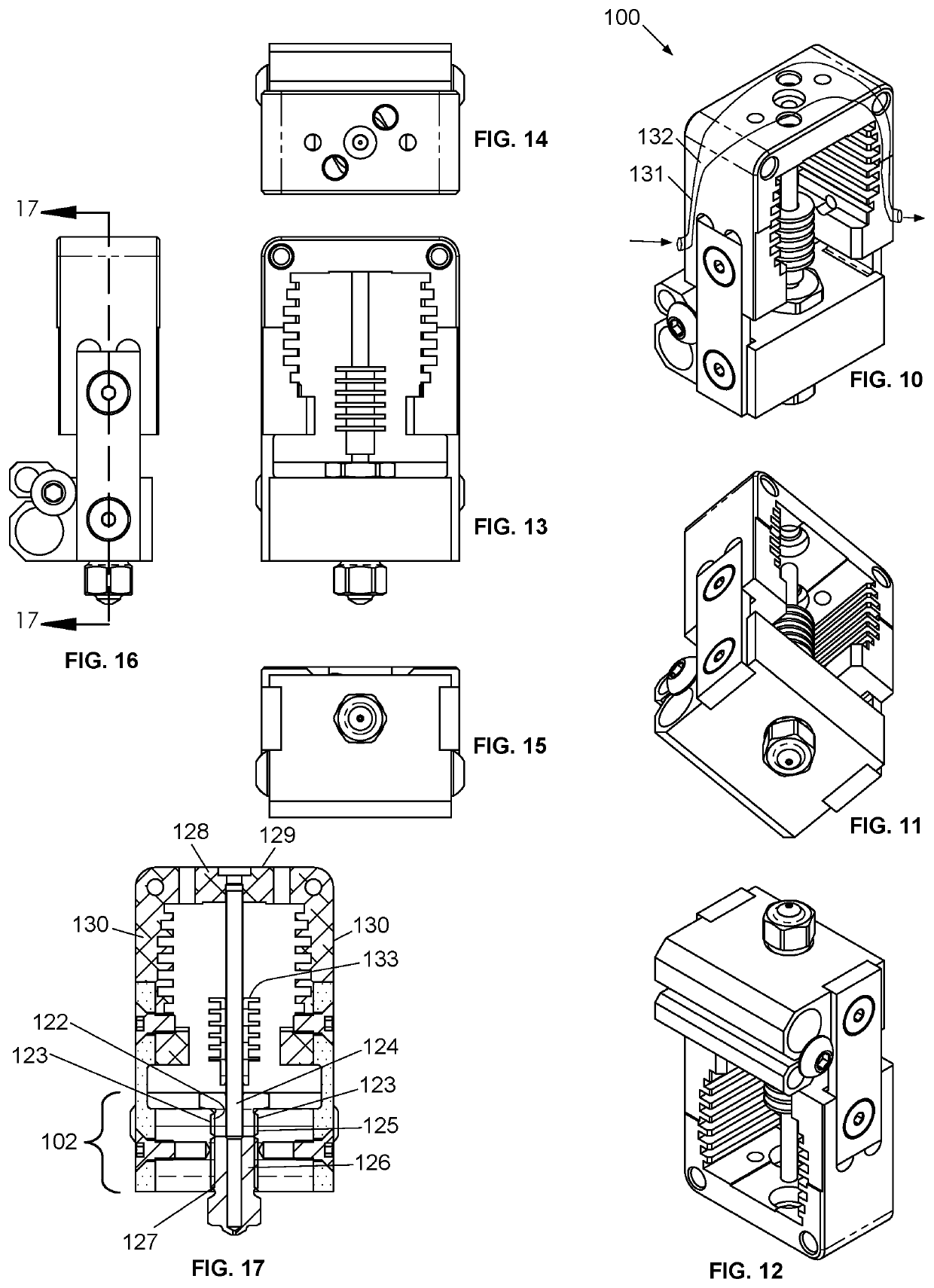
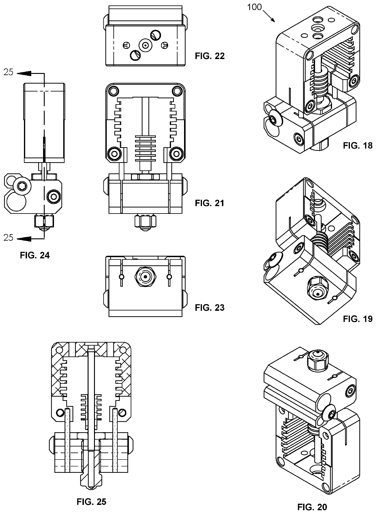
[0046]FIGS. 1 to 33 show exemplary extrusion heads 100 for a three-dimensional printer or similar device 119 also including a supply of filament material 110, a part support base 118, and a mechanism, which can be conventional, for moving the extrusion head 100, the building table 118, or both relative to the other. The extrusion head 100 includes, for example, a cooler 101, a heater 102, a nozzle 103, a feed tube 104, a second cooler 105, a bushing 106, a spacer 107, and a tension member 108.

[0047]The feed tube 104 in this embodiment is made of metal, and extends generally axially. The feed tube 104 has an inlet 104 for receiving a forwardly driven filament 110 of solid deposition material, an outlet 111, a downstream portion 112 adjacent to the outlet 111, an upstream portion 113 upstream from the downstream portion 112, and an internal passage 114 extending from the inlet 104 to the outlet 111.

[0048]The heater 102 is thermally coupled with the downstream portion 112 for heating a...


PUM

PropertyMeasurementUnit
cross-sectional areaaaaaaaaaaa
axial lengthaaaaaaaaaa

Abstract

An extrusion head for a three-dimensional printer is disclosed including a feed tube, a heater, a cooler, and a bridge. The feed tube can be made of metal and has an inlet for receiving a forwardly driven filament of solid deposition material, an outlet, a downstream portion adjacent to the outlet, an upstream portion upstream from the downstream portion, and an internal passage extending from the inlet to the outlet. The heater is thermally coupled with the downstream portion of the feed tube for heating a filament to provide softened fluid deposition material. The cooler is thermally coupled with the upstream portion and spaced generally axially from the heater to define a generally axially extending gap traversed by the feed tube. The bridge traverses the gap and provides a rigid mechanical connection between the heater and the cooler.

Description

CROSS-REFERENCE TO RELATED APPLICATION[0001]This application claims the priority of U.S. Provisional App No. 62 / 507,728, filed May 17, 2017. The entire content of U.S. Provisional App No. 62 / 507,728 is incorporated by reference here.BACKGROUND OF THE INVENTION[0002]The invention relates to the thermal dispensing head for depositing layers of solidifying material in a desired pattern to form three-dimensional physical objects. The modeling material is selected and its temperature is controlled so that it solidifies upon extrusion from the dispensing head onto a base, with the build-up of multiple layers forming the desired article. This method of fabrication is often called Fused Filament Fabrication (FFF), and the thermal dispensing head for a FFF machine is often called the hot end.[0003]Examples of apparatus and methods for FFF of three-dimensional objects by depositing layers of solidifying material are described in Crump U.S. Pat. No. 5,121,329; Batchelder et al. U.S. Pat. No. 5...

Claims


Application Information

Patent Timeline
Patent Type & Authority Patents(United States)
IPC IPC(8): B29C64/209B33Y30/00B29C64/106B29C64/118B29C48/30B29L31/00
CPCB29C64/106B29C64/118B33Y30/00B29C64/209B29L2031/767B33Y10/00
Inventor MONTGOMERY, CHRISTOPHER MARK
Owner SLICE ENG LLC
Why Eureka
Try Eureka