Augmented reality-based system with perimeter definition functionality

a technology of augmented reality and perimeter definition, applied in the field of inspection systems, can solve the problems of high level of skill, detection of objects to be measured, and the measurement process with such a coordinate measuring instrument can be quite complex and time-consuming, and achieve the effect of reducing the number of targets, and improving the accuracy of detection

Active Publication Date: 2021-01-12
LEICA GEOSYSTEMS AG
View PDF13 Cites 0 Cited by
  • Summary
  • Abstract
  • Description
  • Claims
  • Application Information

AI Technical Summary

Benefits of technology

[0012]The reception of a selection of an overlay may be realised in many different ways. In a particular example of an inspection system according to the invention, such a selection may be performed by a user (who is carrying the AR-device) in that the user points with a finger or any pointing device at what he perceives as an overlay associated with a detected structured shape. At least one of the first and second camera units may be configured for recognising this pointing gesture and matching the position of the finger tip with an accordingly located overlay. Another example of selecting an overlay could be a scroll wheel on the AR-device by which a user can scroll through a plurality of overlays assigned to the detected structured shapes, wherein the currently chosen may be marked graphically. With another control function (e.g. pressing the scroll wheel), the selection of a currently chosen overlay can be confirmed, which automatically causes the AR-device to transmit the trigger signal.

Problems solved by technology

A measurement process with such a coordinate measuring instrument can be quite complex and time-consuming, and often requires a high level of skill.
A particular difficulty is the detection of objects to be measured, and the targeting itself.
Unfortunately, inspection systems in the art lack automation and ergonomics for such targeting procedures.
Especially a seamless and immediate interaction between a user and a coordinate measuring instrument is not provided by inspection systems available on the market.

Method used


Image

  • Augmented reality-based system with perimeter definition functionality
  • Augmented reality-based system with perimeter definition functionality

Examples


Embodiment Construction

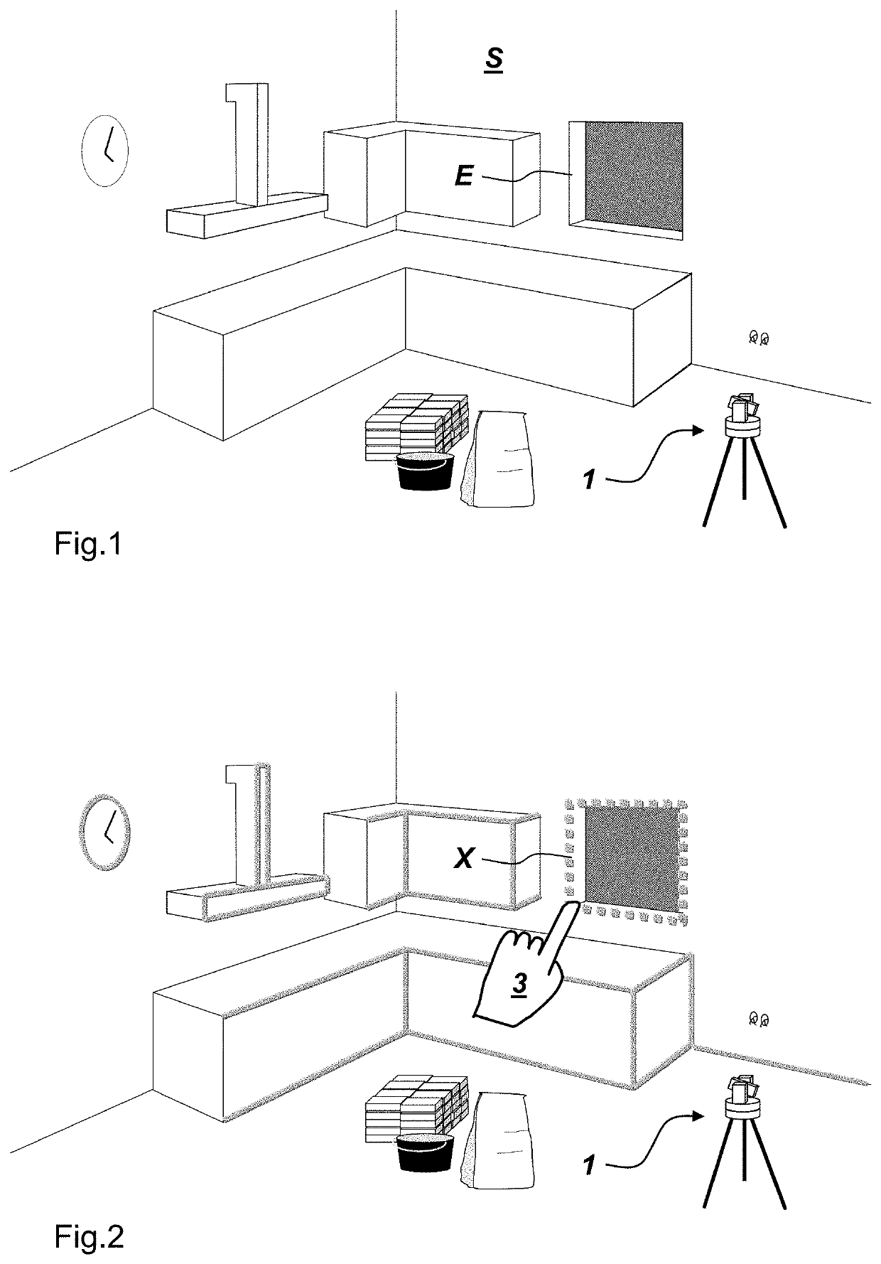
[0039]FIG. 1 shows an exemplary setting S wherein an AR-device is worn by a user (not shown because FIG. 1 shows what a user is seeing when he looks through or at the AR-device) and wherein a coordinate measuring instrument 1 is placed on the floor of the setting. In this embodiment of the inspection system, the coordinate measuring instrument shall be a laser tracker, which is a surveying instrument having a laser unit, an elevative unit, and an azimutal unit. The azimutal unit placed on a tripod and is rotatable about a vertical axis, wherein a first angle encoder can measure this azimutal rotation. The elevative unit is arranged on the azimutal unit and is rotatable about a horizontal axis, wherein a second angle encoder can measure this elevative rotation. By the two rotations, a laser beam emitted by the laser unit can be pointed at various solid angles. The laser tracker can measure points in the setting by a distance measurement (e.g. time of flight, multiple frequency phase-...


PUM


Abstract

An Augmented Reality (AR)-based inspection system comprising a coordinate measuring instrument having a first camera unit, a first computer unit, and a first communication unit, and an AR-device having a second camera unit, a second computer unit, and a second communication unit, wherein the first and the second communication units are connectable, each of the coordinate measuring instrument and the AR-device is configured for establishing a referenced status relative to a setting, at least one of the first and the second computer unit is configured for detecting two-dimensional or three-dimensional structured shapes in images captured by at least one of the first and second camera unit. The AR-device is configured for providing a real view of the setting, providing overlays onto the real view according to corresponding AR-data, wherein said AR-data are at least in part spatially associated with the detected structured shapes.

Description

CROSS-REFERENCE TO RELATED APPLICATIONS[0001]This application claims priority to European Patent Application No. 18155893.3, filed on Feb. 8, 2018. The foregoing patent application are incorporated herein by reference.FIELD OF INVENTION[0002]The present invention relates to an inspection system comprising a coordinate measuring instrument and an Augmented Reality (AR)-device.BACKGROUND[0003]A coordinate measuring instrument of a system according to the invention could be a laser tracker, a laser scanner, a camera system, an articulated arm, a tachymeter, a theodolite, or a total station. Such coordinate measuring instruments feature single point measurements, and in particular also tracking, of near and far objects, and work based on time of flight laser technology, image processing technology, or angle encoder technology.[0004]A measurement process with such a coordinate measuring instrument can be quite complex and time-consuming, and often requires a high level of skill. A partic...

Claims


Application Information

Patent Timeline
Patent Type & Authority Patents(United States)
IPC IPC(8): G01B11/00G01B11/24G06T7/70G06K9/00G01C15/00G06F3/0482
CPCG01B11/005G01B11/002G01B11/24G01C15/002G06K9/00671G06T7/70G06F3/0482G01S17/42G01S7/51G06V20/20
Inventor SAURE, MATTHIASLETTAU, MICHAEL
Owner LEICA GEOSYSTEMS AG
Why Eureka
Try Eureka