
Adaptive transparency of virtual vehicle in simulated imaging system

a virtual vehicle and imaging system technology, applied in scene recognition, instruments, transportation and packaging, etc., can solve the problems of increased hazard for objects moving or having a possibility of starting to move, pedestrians may or may not be easily perceivable, etc., to achieve the effect of improving recognition

Active Publication Date: 2021-01-19
FORD GLOBAL TECH LLC
View PDF9 Cites 7 Cited by
  • Summary
  • Abstract
  • Description
  • Claims
  • Application Information

AI Technical Summary

Benefits of technology

The patent text describes techniques for enhancing the recognition and visual appeal of simulated images. These techniques include adding highlight frames, borders, and depth of field effects to improve the contrast and recognition of objects in the image. These modifications can be based on the size, color, and intensity of the objects in the image. Overall, the patent text provides a way to improve the overall quality and appeal of simulated images.

Problems solved by technology

Objects which are moving or have a possibility of starting to move may be treated as an increased hazard (e.g., by detecting significant translation of a pixel region centroid of the object from frame to frame, and / or using sensor fusion).
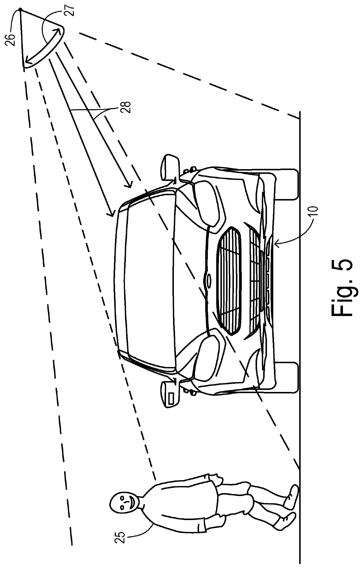
For example, a pedestrian may be half obscured, but given the contrast difference between the, person's clothing and the image background (e.g., tone, hue, texture, etc.,) the pedestrian may or may not be easily perceivable.

Method used


Image

  • Adaptive transparency of virtual vehicle in simulated imaging system
  • Adaptive transparency of virtual vehicle in simulated imaging system
  • Adaptive transparency of virtual vehicle in simulated imaging system

Examples


Embodiment Construction

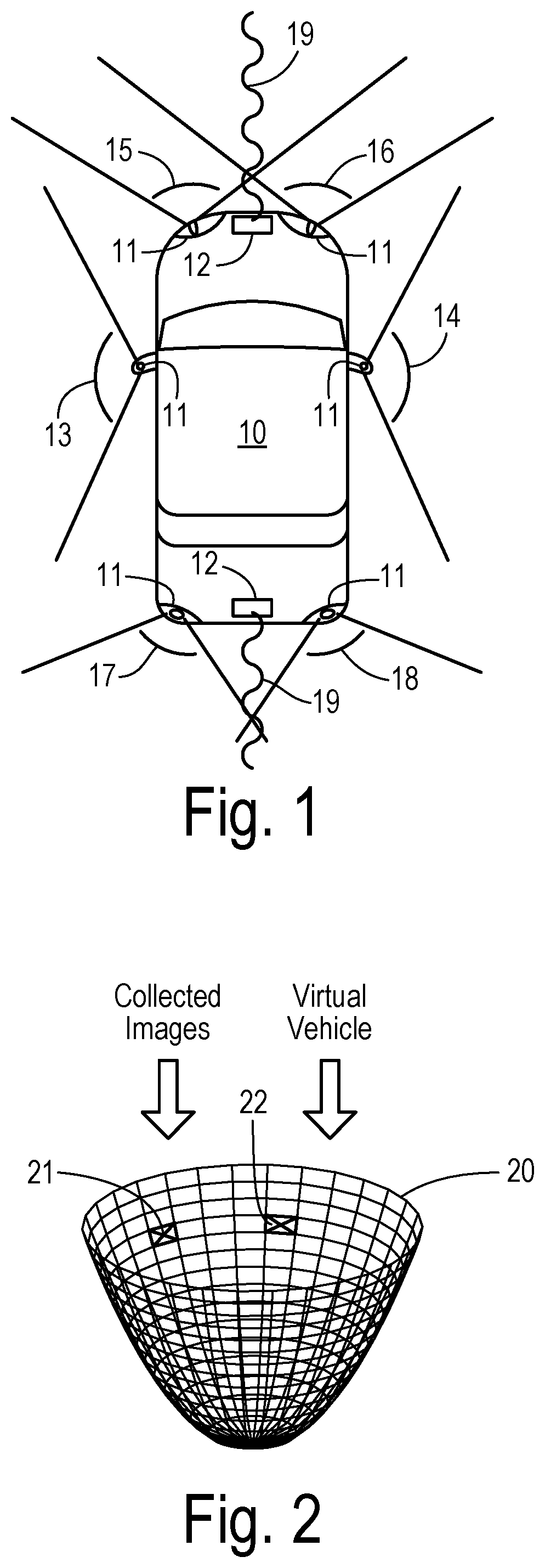
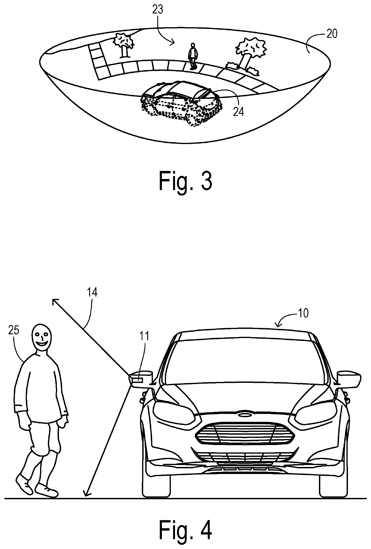
[0028]Referring to FIG. 1, a vehicle 10 (such as a passenger car) has an array of cameras comprised of cameras 11 mounted at various points around the perimeter of vehicle 10. Cameras 11 may be integrated into the side view mirror assemblies and / or the front and rear exterior lighting units, for example. Cameras 11 provide respective fields of view 13-18, resulting in outward-looking, exterior image data surrounding vehicle 10 with full coverage over 360°. Vehicle 10 also has various active remote sensors, such as front and rear radar units 12 which transmit and receive radar signals 19 for detecting and classifying nearby objects. Other active sensors include ultrasonic and laser sensors, all of which are used in the art of motor vehicles for obstacle detection, adaptive cruise control, lane tracking, parking assistance, and other advanced features. Such sensors, specifically their output or fusion thereof, may be used to further augment the virtual view by displaying indications o...


PUM


Abstract

A visual scene around a vehicle is displayed to an occupant of the vehicle on a display panel as a virtual three-dimensional image from an adjustable point of view outside the vehicle. A simulated image is assembled corresponding to a selected vantage point on an imaginary parabolic surface outside the vehicle from exterior image data and a virtual vehicle image superimposed on a part of the image data. Objects are detected at respective locations around the vehicle subject to potential impact. An obstruction ratio is quantified for a detected object having corresponding image data in the simulated image obscured by the vehicle image. When the detected object has an obstruction ratio above an obstruction threshold, a corresponding bounding zone of the vehicle image is rendered at least partially transparent in the simulated image to unobscure the corresponding image data.

Description

CROSS REFERENCE TO RELATED APPLICATIONS[0001]Not Applicable.STATEMENT REGARDING FEDERALLY SPONSORED RESEARCH[0002]Not Applicable.BACKGROUND OF THE INVENTION[0003]The present invention relates in general to in-vehicle display or remote monitoring of a virtual scene surrounding a motor vehicle, and, more specifically, to displaying an outside surround view including a virtual representation of the vehicle itself.[0004]Surround view camera systems are known in the art for providing a driver of a vehicle with a synthesized view of the environment and objects around a motor vehicle from the perspective of a viewpoint which is outside the vehicle. To provide realism, a virtual image of the vehicle itself is added to the synthesized view. The driver can typically select from viewpoints (or viewpoints may be automatically selected) at locations ranging 360° around the vehicle and usually at a height at or above the height of the vehicle. The resulting movable, simulated image provides both ...

Claims


Application Information

Patent Timeline
Patent Type & Authority Patents(United States)
IPC IPC(8): G06K9/00G06T7/73G06T7/215B60R11/04
CPCG06K9/00805B60R11/04G06K9/00369G06K9/00671G06T7/215G06T7/73G08G1/166G06T17/00G06V40/10G06V20/584G06V20/58B60R1/27B60R2300/102B60R2300/307B60R2300/308B60R2300/8093G06T11/00G06V20/20G06V40/103
Inventor HERMAN, DAVID M.
Owner FORD GLOBAL TECH LLC
Learn More