Supercharge Your Innovation With Domain-Expert AI Agents!

Optical imaging device and cap

a technology of optical imaging and cap, applied in the field of optical imaging, can solve the problems of compression of brain tissue, subdural hematoma, and particularly serious hematomas inside the skull

Active Publication Date: 2021-01-26
ARCHEOPTIX BIOMEDICAL
View PDF18 Cites 0 Cited by
  • Summary
  • Abstract
  • Description
  • Claims
  • Application Information

AI Technical Summary

Benefits of technology

The present invention provides an optical imaging device and a removable cap for use with the imaging device. The cap has a mounting surface with a plurality of openings that receive the first and second optical transceivers. The cap includes a bellow support plate and a deformable bellow sealingly engaged to the bellow support plate. The bellow has a C-shaped cross-sectional profile that sealingly engages the bellow support plate and contacts the surface of the object to be imaged. The fixed and deformable housings have tips that contact the surface of the object to be imaged. The technical effects of the invention are improved optical imaging and easy removal and replacement of the cap.

Problems solved by technology

Hematomas inside the skull are particularly serious, because they can produce local pressure on the brain.
Subdural hematomas are usually the result of serious head injury.
Acute subdural hematomas are among the deadliest of head injuries as the bleeding fills the brain area very rapidly, thereby compressing brain tissue, which can lead to brain injury.
In the elderly, such veins are often stretched because of brain atrophy or shrinkage and thus are more easily injured.
Although CT scanning and MRI are imaging techniques that can be used to identify and locate traumatic intracranial hematomas, all medical facilities (e.g., trauma centers) do not necessarily have immediate CT scanning and MRI capability on a 24 / 7 basis and thus it may not be possible in such cases for such scans to be performed so that an identified hematoma can be evacuated within the desired time frame.
Also, timely identification of patients that require surgery for dealing with the hematoma can be more difficult in emergencies involving head trauma in underdeveloped areas of the world, or in areas which have limited access to trauma centers having 24 / 7 CT scanning or MRI capability or which have travel time issues from the site of the injury to the treatment facility, e.g., a rural area or a battlefield.
A neurological exam, however, is a poor substitute for a CT scan because no single physical sign can reliably indicate the presence of a hematoma.

Method used


Image

  • Optical imaging device and cap
  • Optical imaging device and cap
  • Optical imaging device and cap

Examples


example 1

Optical Imaging Device

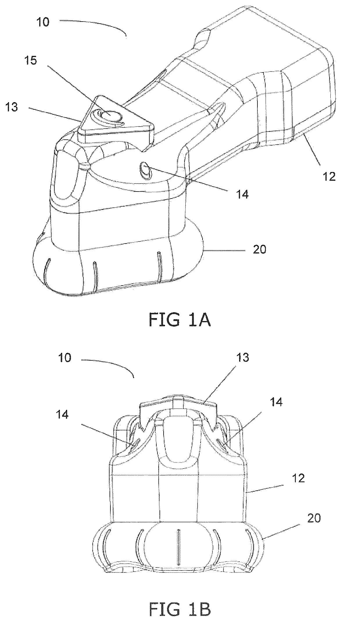
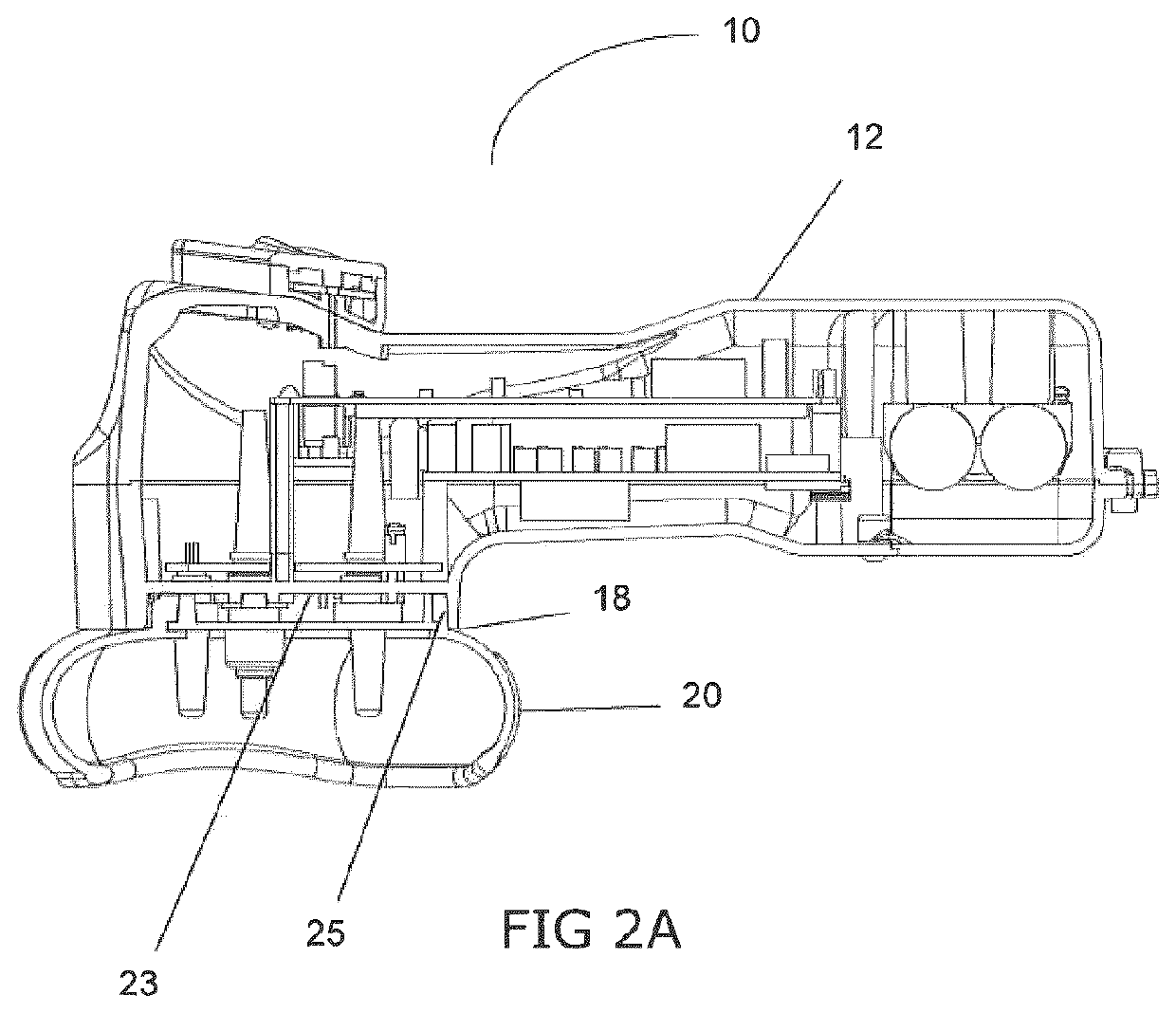
[0115]FIGS. 1A and B and 2A and B depict one embodiment of a handheld optical imaging device 10 in accordance with the present invention. The optical imaging device 10 comprises a removable cap 20 attached to body 12 suitably sized and shaped to easily fit within the hand of a user.

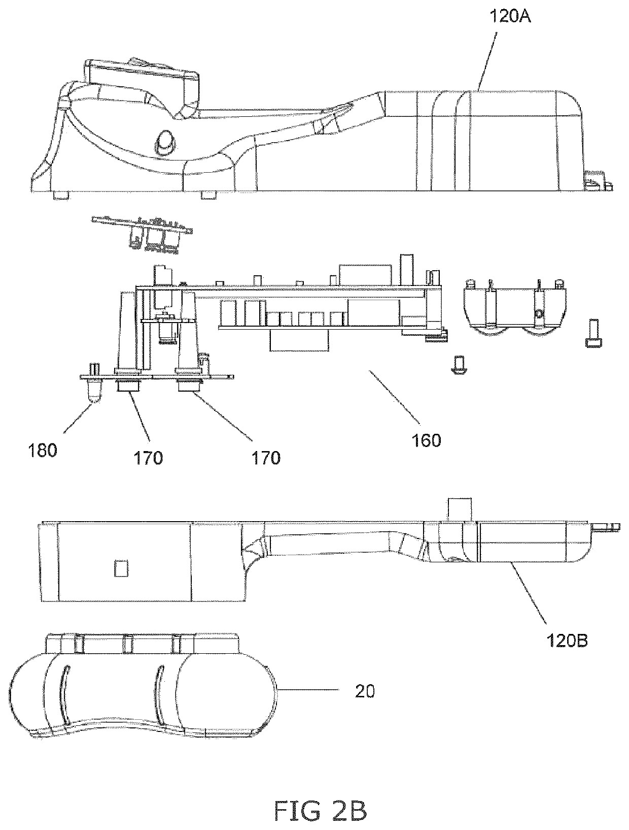
[0116]In the embodiment depicted in FIGS. 1A and B and 2A and B the device comprises one NIR light source 180, and four NIR light detectors 170.

[0117]An exploded view of this embodiment of the optical imaging device is provided in FIG. 2B. FIG. 2B depicts two part housing 120A,B that forms the body. Housing 120A,B is designed to contain within it the electronics 160 required for function, as well as the processor required to analyze the data obtained during the imaging process.

example 2

Optical Imaging Device

[0118]FIGS. 7A-C and 8 depict another embodiment of a handheld optical imaging device 100 in accordance with the present invention. The optical imaging device 100 comprises a removable cap 200 attached to a body suitably sized and shaped to easily fit within the hand of a user.

[0119]In the embodiment depicted in FIGS. 7A-C and 8, the device comprises one NIR light source 880, and four NIR light detectors 870.

[0120]An exploded view of this embodiment of the optical imaging device is provided in FIG. 8. FIG. 8 depicts two part housing 820A,B that forms the body. Housing 820A,B is designed to contain within it the electronics 860 required for function, as well as the processor required to analyze the data obtained during the imaging process.

[0121]Prior to use, removable cap 200 is installed via attachment to fixed base plate 300. The device is powered by a battery (not shown).

example 3

litary Flashlight / Optical Imaging Device

[0122]FIGS. 18 to 20 depict an alternative embodiment of a handheld optical imaging device 700 in accordance with the present invention. This embodiment is based on a modification of a standard issue military flashlight. In this embodiment, the optical imaging device 700 comprises a removable cap 725 attached to the main body 720 of a military flashlight, wherein the head 710 of the flashlight is provided with a cap port 730 for receiving the removable cap 725, in addition to the standard flashlight function. When not in use as an optical imaging device, the removable cap 725 is removed and the cap port 730 is covered by a port cover 735, as depicted in FIG. 19. Prior to use as an imaging device, the removable cap 725 is installed via attachment to the cap port 730.

[0123]FIG. 18 depicts the military embodiment with the removable cap 725 installed in the cap port 730.

[0124]In the embodiment depicted in FIG. 20, the device comprises one NIR ligh...


PUM

PropertyMeasurementUnit
inner volumeaaaaaaaaaa
perimeteraaaaaaaaaa
circumferenceaaaaaaaaaa

Abstract

The present invention provides a removable optical imaging device cap for use with a near infrared (NIR) light optical imaging device for detecting intracranial hematoma.

Description

CROSS-REFERENCE TO RELATED APPLICATIONS[0001]This application is the United States national phase of International Application No. PCT / CA2016 / 050341 filed Mar. 23, 2016, and claims benefit of U.S. Provisional Patent Application No. 62 / 136,781 filed Mar. 23, 2015, the disclosures of which are hereby incorporated in their entirety by reference.FIELD OF THE INVENTION[0002]The present invention pertains to the field of optical imaging and in particular to devices for optical imaging to detect hematoma.BACKGROUND[0003]A hematoma is a localized collection of extravasated blood (e.g., blood from a ruptured blood vessel or the like), usually clotted, in an organ, space, or tissue; bruises and black eyes are familiar forms that are seldom serious. Hematomas can occur almost anywhere on the body including inside the skull, and are almost always present with a fracture; in minor injuries the blood is absorbed unless infection develops.[0004]Hematomas inside the skull are particularly serious, ...

Claims


Application Information

Patent Timeline
Patent Type & Authority Patents(United States)
IPC IPC(8): A61B5/02A61B5/00
CPCA61B5/02042A61B5/0042A61B5/0066A61B5/4064A61B5/4887A61B5/6814A61B5/7282A61B2560/0406A61B2560/0431A61B2562/146A61B2562/185A61B90/00G01J1/04
Inventor STRATIS, SAVVASHENDERSON, JAMES PATRICKRILEY, JASON DAVID RICHARD
Owner ARCHEOPTIX BIOMEDICAL
Features
  • R&D
  • Intellectual Property
  • Life Sciences
  • Materials
  • Tech Scout
  • Unparalleled Data Quality
  • Higher Quality Content
  • 60% Fewer Hallucinations
Learn More